Knock sensor
Filter settings
Signal gain
Sensor signal gain control
Frequency 1/2 and RPM
These parameters set the knock sound filtering frequency.
You can set different frequencies for low and high engine speeds. It can improve knock detection for some engines.
In most cases, a single knock frequency is sufficient for the entire RPM range. To achieve this - set the RPM setting above Max engine RPM, and use the Frequency 1 option only.
Chart
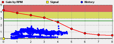
Gain by RPM
Red line sets signal gain by RPM. With RPM rising, gain should be decreased.
Signal
Yellow marker displays the current signal value from the sensor
Knock treshold
Green line displays the specified knock threshold
History
Blue dots show knock signal history. History is displayed after opening the log file.
Knock Frequency Calculator
The sound of knock is the sound of the resonating piston. The frequency of the sound is mostly dependend on the piston diameter. In addition to the main frequency, the harmonic is well audible at a 2x frequency. In some cases, the best results are achieved when tuning filter to the 2x frequency.
Knock spectre sample:

Knock control
Knock treshold
Specifies the threshold above which the signal from the sensor is considered as knock. The threshold is displayed on the graph with the green line.
Retard
Specifies the retard rate, in degrees/volts exceeding the detonation threshold, and the retard limit.
For example, if retard rate is 1deg/cycle:
- When the threshold is exceeded by 2 volts, ignition is retarded by 2deg.
- When the threshold is exceeded by 1 volt, ignition is retarded by 1deg.
- When the threshold is exceeded by 0.5 volts, ignition is retarded by 0.5deg.
If knock is detected, then ignition in the current cylinder is retarded. Other cylinders are also partially retarded, to prevent further knock.
Recovery
Specifies the ignition recovery rate. If knock is not observed, then retard will be reduced with the specified speed.
Ignore knock if MAP below
Ignores the knock sensor on light loads. Helps to filter out knock-like engine noise.
Per sylinder sensor selection
Specifies, which sensors should be used for each cylinder.
Tuning procedure
Sensor health check
- Connect the knock sensor
- Set the knock frequency 5.12 kHz
- Turn on Tacho/Knock test
- Knock on the sensor using metal thing.
- Check the readings of the sensor voltage - it must respond to knocking
Basic setting
- Set the knock frequency
- Set the gain to 20
- Set the knock control parameters:
- Treshold 3V
- Retard 1 deg/cycle, max 5 deg
- Recovery 0.13 deg/cycle
- Draw gain by RPM as on picture below
Calibration by RPM
- Warm up the engine
- Adjust the gain to set signal level into 2..2.5V range
- Slowly increase RPM to the maximum. Knock signal have to be in 2..2.5V range. If necessary - adjust gain by RPM.
- Set safe and retarded advance, and make several accelerations from idle to the max RPM.
- Knock signal have to be in 2.5..3V range. If necessary - adjust gain by RPM.
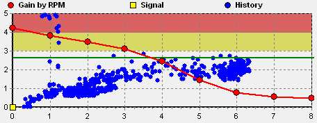
With proper configuration, the log should look like this. The majority of the blue points should be at the 2-3 volts.
Tuning tips
Optimal ignition advance is not always at the knock treshold.
Proper setting is when the knock is not existent during normal engine operation.
To adjust signal filter settings properly, it's necessary to use headphones to control engine noise by ear.
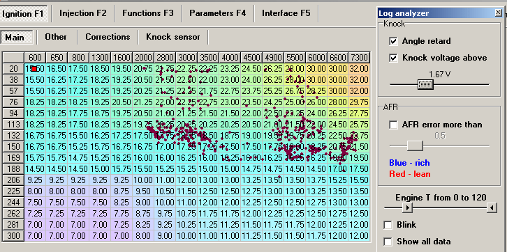
Use Log Analyzer feature to overlay knock points on the Ignition Advance table