Introduction

Invent Jetronic is designed to replace mechanical KE-Jetronic system with electronic fuel injection.
Before installation - read this manual carefully.
If you're using mobile device - press Menu button at the top left corner.

Installation
Audi 5 cylinders 2.3/2.0
Engine codes AAR,NF,NG,RT,PS Two-piece intake manifold
Begin by removing the intake hose. Additionally, detach the smaller hoses.
Removing mechanical injector
Detach the mechanical injectors along with the distributor.
Remove the upper half of the intake manifold.

Remove the throttle damper located beneath the throttle assembly to allow the installation of the fuel rail.

Remove the MAF air plate and secure the moving component with a plastic strap.

Cut the start injector mount to allow the installation of the fuel rail.

Injector sleeves
Install new injector sleeves.

Fuel rail
Install the injectors into the fuel rail. Lubricate the O-rings with water, then position the rail with the injectors securely in place.
Bend the metal brackets of the rail and drill a hole in each bracket to insert the screw that will secure it to the intake manifold.
Ensure the injectors are fully inserted without any misalignment.

Fuel lines and filter
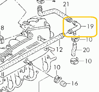
The fuel lines are now ready for installation.

The metal cylinder with three fittings serves as both a fuel filter and a pressure regulator, necessitating the removal of the old original unit.
- Connect the feeding line from the fuel pump to the "IN" fitting.
- Attach the return line, which goes back to the tank, directly to the unnamed central fitting.
- Connect the main line leading to the fuel rail to the "OUT" fitting.
Utilize the three black junctions included in the kit to connect the rubber line to the filter/pressure regulator, ensuring they are securely mounted.

Once the fuel lines are installed, cycle the ignition on and off 5-6 times without engaging the starter to build pressure in the fuel lines.
Thoroughly inspect for any potential leaks.
The fitting features a cone-shaped seal that tightens under fuel pressure. If you notice a leak, try gently moving the fitting back and forth. If it continues to leak, remove it and apply a small amount of oil to the sealing parts.
Idle control valve (ICV)
Clean the valve internals using carburetor cleaner and lubricate them with oil. Avoid using WD-40, as it is not a good lubricant. Bicycle chain lubricant is well suitable for this purpose.
To install the valve, gently adjust its mount to position the valve closer to the engine block.

In some versions of the engine, the idle air path has a restrictor in the plastic pipe marked yellow, which can prevent the normal operation of the ICV. This restrictor should be deleted.
Intake air heater
The 2.3 engine features an automatic intake air heating shutter designed to maintain the intake air temperature above 10-20 degrees. Ensure this valve is functioning correctly. A malfunctioning valve can cause the throttle valve and IAC to freeze, resulting in difficulties with cold starts and idling.
The precise placement of the MAP sensor is crucial for optimal engine performance. Please position the MAP sensor exactly as shown on the photo
Drill a 13mm hole for the sensor and an 8mm hole for the securing bolt. Apply grease to the drill tip to capture debris. It is recommended to clean the intake manifold thoroughly after drilling to ensure no metal debris remains.
Apply a sealant to fill the hole, ensuring an adequate amount of sealing paste is used due to the rough surface of the intake manifold.
Secure sensor with included screw. Apply sealant to the thread, to prevent air leaks and unscrewing.
Never install the sensor with the wires facing upwards to prevent water from running along the cable, which could lead to connector flooding and subsequent oxidation.
Secure the sensor using the screw. Apply sealant to the threads to prevent air leaks and ensure the sensor remains securely fastened.
Warning
Installing a MAP sensor in place of a cold start injector is strictly prohibited.

ECU and wiring
Warning
Disconnect the battery when servicing the electrical system. Reconnect the battery only when the engine needs to be started.
The ECU is designed to be dust and splash-resistant but is not suitable for continuous exposure to water or pressurized water. It is recommended to install it in a dry and secure location. Ensure that the ECU is not installed with the cable facing upwards, as this may allow water and moisture to enter the unit.

Warning
Wire colors may change without prior notice. If wires have text labels, use these labels to identify the purpose of each wire.
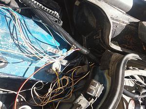
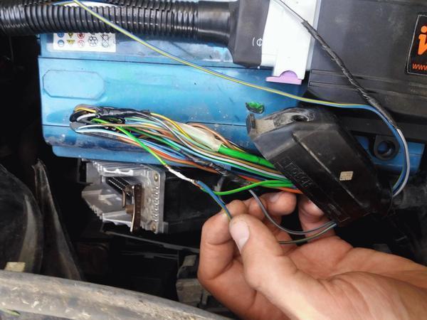
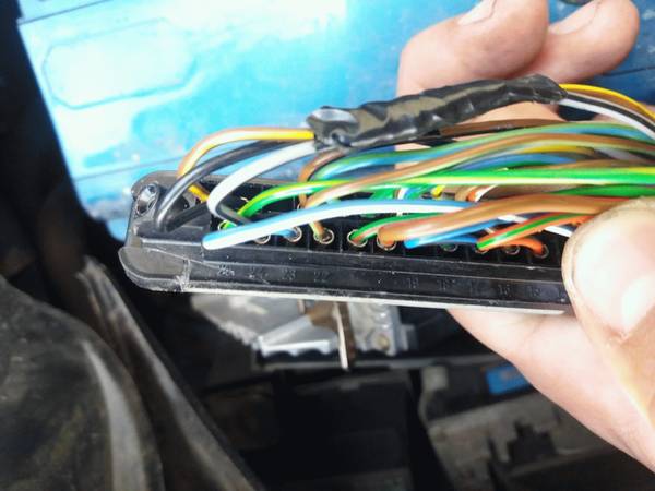
This is the wiring.

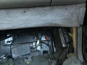
This photo provides an overview of the installation, including key mounting points. The ECU is installed in the position formerly occupied by the mechanical injection distributor. Begin the wiring process by locating the ECU and connecting the injectors. Once these components are connected, the remaining wiring will naturally fall into place.

AFS emulator
Attention
For the RT engine, the AFS emulator is unnecessary. Please proceed to the next chapter.
Plastic box #1 must be removed from the distributor while remaining connected; otherwise, the stock ECU will display an error.

Remove the middle wire from connector #2 and connect it to the EMUL wire.

It should be insulated using shrink tubing or electrical tape.

Measure the resistance between pins 1 and 3 of connector #2. It should be between 3 and 5 kOhms. If the resistance is outside this range, inspect the wires near the connector for signs of oxidation or damage.
Connector #2 should be reconnected to its original position
Hall sensor
Locate the hall sensor connector on the ignition distributor.

Connect the DH wire in parallel to the central wire of the Hall sensor connector.


Lambda sensor
Connect the LAMBDA wire to the signal wire of the lambda probe (refer to the attached photo).
Attention
Ensure the lambda is disconnected from the stock ECU to prevent any interference.

How to install an aftermarket sensor
Throttle position switches
Disconnect the stock connector and measure the resistance of the idle switch. The resistance should be between 0 and 5 Ohms. If it exceeds this range, the switch is likely worn out and should be replaced.

Connect the IDLE SW in parallel with the idle switch wire (position #1 at the connector).
Connect the FULL SW in parallel with the full throttle switch wire (position #3 at the connector). If there is no full throttle switch, insulate this wire. The ECU can operate without it.

Coolant temperature sensor
The CLT wire should be connected in parallel to pin #2 (black-red) of the coolant temperature sensor. If the wire colors differ, use a multimeter to identify the correct pin. The correct pin will show a 5V reading when the connector is disconnected from the sensor.

Idle valve
Disconnect the old idle valve connector and connect the new one labeled "IDLE."
Attention
Only a 2-wire idle valve is supported. An external circuit is required for a 3-wire valve. For further details, please refer to the Additional Information section at the end of the document.
Power
Connect the power wires to the battery and securely mount the main relay in close proximity to the battery.
Attach the COIL +12 wire to the +12V terminal of the ignition coil. This wire is responsible for activating the main relay.
LPG
Connect the EXT wire to the gas supply valve and activate the LPG mode by EXT input in the settings. The ECU will then adjust to operate on gas fuel.
For carburetted LPG systems, it is unnecessary to disconnect the power from the gasoline injectors. Simply select the Turn off injection option, and the fuel supply will be interrupted by the signal from the EXT. Connect the EXT wire to the gas supply valve and activate the LPG mode by EXT input in the settings. The ECU will then adjust to operate on gas fuel.
Air conditioner
Connect the AC (or EXT) wire to the air conditioner clutch wire. This connection is essential for maintaining the idle RPM when the air conditioner is engaged.
K-Line
To connect the K-Line cable, you will need to prepare three wires: Typically, the Bluetooth interface is used to connect to the ECU. However, in rare instances where the Bluetooth connection proves unreliable, the K-Line can be utilized as an alternative.
To connect the K-Line cable, you need 3 wires:
- 12V
- Ground
- K-line
Pinout of the K-Line cable:

Pinout of the car OBD2 connector

Other wires
This manual does not mention certain additional wires, which are reserved for future use. Please ensure that any unused wires are isolated and concealed within the harness.
Distributor
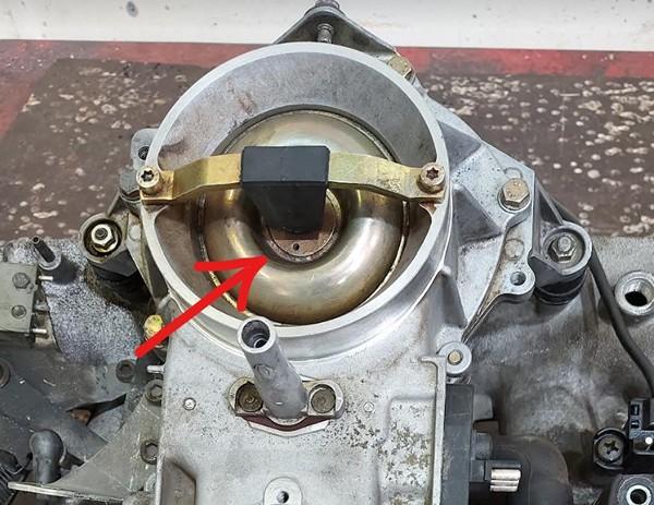
Distributor check for AAR engine
Attention
Please ensure that the sensing element is positioned opposite the connector. If the Hall sensor is placed adjacent to the connector, the ignition system may malfunction. It is advisable to replace the sensor with the appropriate one.
The correct hall sensor for the AAR engine is shown in the photo.

- VAG 030 905 065 B
- OSSCA 05430
- JP GROUP 1191400300
Distributor preparation for phased injection
This operation is optional. If performed, it will enable sequential phased injection, which is essential for CNG/LPG conversion. For petrol engines, batch injection is ok. However, phased injection can enhance fuel economy slightly during cruising.
This manual is applicable regardless of the distributor model or rotation direction. If your distributor differs from the one shown in the photo, simply adhere to the instructions in the manual to achieve the proper result.
Place a mark on the distributor case

Take off the distributor cap. Turn the crankshaft to align the rotor with the mark.

Position the engine at Top Dead Center (TDC). The rotor should remain aligned with the mark.

Remove the rotor and the plastic cap. Mark the window edge at the center of the hall sensor. The marked window edge should then be widened.

Please widen the window edge by precisely 1.1mm. Ensure maximum precision in this adjustment. If the PHASE indicator in the program becomes unstable, increase the window width by an additional 0.1mm. Conversely, if the window becomes too wide, idling may become unstable.

The cut window will function as the first cylinder marker for the ECU.
Additional info
Wiring diagram for Audi 2.3 AAR engine

- 2 - EVAP valve
- 3 - fuel pump
- 6 - idle valve
- 10 - ignition amplifier
- 11 - ignition coil
- 16 - cold start injector
- 21 - injection pressure regulator
- 36 - throttle switches
- 37 - lambda sensor
- 40 - hall sensor
- 42 - coolant temperature sensor
- 45 - knock sensor
- 50 - airflow sensor
- 51 - atmospheric pressure sensor
- 80 - air conditioner
- 84 - instrument cluster
- 91 - fuel pump relay
- 100 - injection ECU
- 103 - ignition ECU
Wiring diagram for Audi 2.0 RT engine

- 3 - fuel pump
- 6 - idle valve
- 10 - ignition amplifier
- 11 - ignition coil
- 16 - cold start injector
- 21 - injection pressure regulator
- 36 - throttle switches
- 37 - lambda sensor
- 40 - hall sensor
- 42 - coolant temperature sensor
- 45 - knock sensor
- 48 - coolant thermo switch
- 50 - airflow valve position sensor
- 84 - instrument cluster
- 87 - start signal
- 91 - fuel pump relay
- 100 - injection ECU
- 103 - ignition ECU
MAP sensor pinout

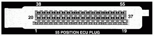
Invent Jetronic ECU pinout
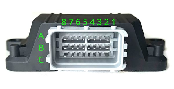
| 8 | 7 | 6 | 5 | 4 | 3 | 2 | 1 | |
| A | IDLE | INJ1 | INJ2 | INJ3 | INJ4 | INJ5 | INJ6 | X1** |
| B | +12V | CLT | TPS | AN | KLINE | EMUL | IDLE SW | FULL SW |
| C | GND | 5V OUT | IAT | MAP | LAMBDA | EXT | DH | AC* |
() - available in version 2.3 (*) - available in version 2.5
3-wire IAC valve
This valve contains two windings: one for opening and another for closing.
An external circuit is necessary to connect this valve. A MOSFET capable of handling over 5A of current and more than 55V of voltage is used (for example IRFZ44)
The dotted line represents the IAC case

Abbreviations
- MAP - absolute pressure sensor
- TPS - throttle position sensor
- IAT - sensor air temperature
- CLT - coolant temperature sensor
- DH - Hall sensor
- AFS - airflow sensor
Audi 4/5 cylinders
Single-piece intake manifold
5-cyl engines: HX,HY,JT,KE,KF,KK,KL,KU,KV,KX,KZ,PR,PX,WB,WC,WG,WK,WU
4-cyl engines: AAD, ACE, 9A, PL
This manual is based on the 5-cylinder engine. The 4-cylinder engine is fundamentally similar, with minor differences in layout and one fewer cylinder.
Video of installation on VW 16V engine

Removing mechanical injector
Detach the mechanical injectors along with the distributor.
The airflow sensor plate is no longer required. Remove it and secure the moving component beneath with a plastic strap.
Bend the injector ventilation pipe to allow the installation of the fuel rail.

Injector sleeves
Attention
In rare instances, sleeves are entirely constructed from plastic. It is required to replace them with metal ones, as illustrated in the images below.
Carefully unscrew the injector sleeves, ensuring caution as the sleeves consist of three parts that may fall into the engine.


The plastic component can be removed using the thread tap.

We only need this part. Reinstall it using engine sealant.

Install additional O-rings on the injectors. Lubricate the O-rings, then insert the injectors into the sleeves until they click into place.

The O-ring on the injector tip must be properly seated.

Fuel rail
Lubricate the O-rings with water and position the fuel rail appropriately.
Bend the metal brackets of the rail and drill a hole in each bracket to insert the screw that will secure it to the intake manifold.
Ensure the injectors are fully inserted without any misalignment.
Fuel lines and filter
The fuel lines are now ready for installation.
The metal cylinder with three fittings serves as both a fuel filter and a pressure regulator, necessitating the removal of the old original unit.
- Connect the feeding line from the fuel pump to the "IN" fitting.
- Attach the return line, which goes back to the tank, directly to the unnamed central fitting.
- Connect the main line leading to the fuel rail to the "OUT" fitting.
Utilize the three black junctions included in the kit to connect the rubber line to the filter/pressure regulator, ensuring they are securely mounted.
Once the fuel lines are installed, cycle the ignition on and off 5-6 times without engaging the starter to build pressure in the fuel lines.
Thoroughly inspect for any potential leaks.
The fitting features a cone-shaped seal that tightens under fuel pressure. If you notice a leak, try gently moving the fitting back and forth. If it continues to leak, remove it and apply a small amount of oil to the sealing parts.
Idle valve
Clean the valve internals using carburetor cleaner and lubricate them with oil. Avoid using WD-40, as it is not a good lubricant. Bicycle chain lubricant is well suitable for this purpose.
MAP sensor
The precise placement of the MAP sensor is crucial for optimal engine performance. Please position the MAP sensor exactly as shown on the photo
Drill a 13mm hole for the sensor and an 8mm hole for the securing bolt. Apply grease to the drill tip to capture debris. It is recommended to clean the intake manifold thoroughly after drilling to ensure no metal debris remains.
Apply a sealant to fill the hole, ensuring an adequate amount of sealing paste is used due to the rough surface of the intake manifold.
Secure sensor with included screw. Apply sealant to the thread, to prevent air leaks and unscrewing.
Never install the sensor with the wires facing upwards to prevent water from running along the cable, which could lead to connector flooding and subsequent oxidation.
Secure the sensor using the screw. Apply sealant to the threads to prevent air leaks and ensure the sensor remains securely fastened.
Warning
Installing a MAP sensor in place of a cold start injector is strictly prohibited.


ECU and wiring
Warning
Disconnect the battery when servicing the electrical system. Reconnect the battery only when the engine needs to be started.
The ECU is designed to be dust and splash-resistant but is not suitable for continuous exposure to water or pressurized water. It is recommended to install it in a dry and secure location. Ensure that the ECU is not installed with the cable facing upwards, as this may allow water and moisture to enter the unit.
Warning
Wire colors may change without prior notice. If wires have text labels, use these labels to identify the purpose of each wire.
This is the wiring configuration.
The wiring harness for 4-cylinder and 5-cylinder engines is identical. For a 4-cylinder engine, leave the connector for injector #5 unconnected.
This photo provides an overview of the installation, including key mounting points. The ECU is installed in the position formerly occupied by the mechanical injection distributor. Begin the wiring process by locating the ECU and connecting the injectors. Once these components are connected, the remaining wiring will naturally fall into place.
AFS emulator
Attention
For the RT engine, the AFS emulator is unnecessary. Please proceed to the next chapter.
Plastic box #1 must be removed from the distributor while remaining connected; otherwise, the stock ECU will display an error.
Remove the middle wire from connector #2 and connect it to the EMUL wire.
It should be insulated using shrink tubing or electrical tape.
Measure the resistance between pins 1 and 3 of connector #2. It should be between 3 and 5 kOhms. If the resistance is outside this range, inspect the wires near the connector for signs of oxidation or damage.
Connector #2 should be reconnected to its original position
Hall sensor
Locate the hall sensor connector on the ignition distributor.
Connect the DH wire in parallel to the central wire of the Hall sensor connector.
Lambda sensor
Connect the LAMBDA wire to the signal wire of the lambda probe (refer to the attached photo).
Attention
Ensure the lambda is disconnected from the stock ECU to prevent any interference.
How to install an aftermarket sensor
Throttle position switches
Disconnect the stock connector and measure the resistance of the idle switch. The resistance should be between 0 and 5 Ohms. If it exceeds this range, the switch is likely worn out and should be replaced.
Connect the IDLE SW in parallel with the idle switch wire (position #1 at the connector).
Connect the FULL SW in parallel with the full throttle switch wire (position #3 at the connector). If there is no full throttle switch, insulate this wire. The ECU can operate without it.
Coolant temperature sensor
The CLT wire should be connected in parallel to pin #2 (black-red) of the coolant temperature sensor. If the wire colors differ, use a multimeter to identify the correct pin. The correct pin will show a 5V reading when the connector is disconnected from the sensor.
Idle valve
Disconnect the old idle valve connector and connect the new one labeled "IDLE."
Attention
Only a 2-wire idle valve is supported. An external circuit is required for a 3-wire valve. For further details, please refer to the Additional Information section at the end of the document.
Power
Connect the power wires to the battery and securely mount the main relay in close proximity to the battery.
Attach the COIL +12 wire to the +12V terminal of the ignition coil. This wire is responsible for activating the main relay.
LPG
Connect the EXT wire to the gas supply valve and activate the LPG mode by EXT input in the settings. The ECU will then adjust to operate on gas fuel.
For carburetted LPG systems, it is unnecessary to disconnect the power from the gasoline injectors. Simply select the Turn off injection option, and the fuel supply will be interrupted by the signal from the EXT. Connect the EXT wire to the gas supply valve and activate the LPG mode by EXT input in the settings. The ECU will then adjust to operate on gas fuel.
Air conditioner
Connect the AC (or EXT) wire to the air conditioner clutch wire. This connection is essential for maintaining the idle RPM when the air conditioner is engaged.
K-Line
To connect the K-Line cable, you will need to prepare three wires: Typically, the Bluetooth interface is used to connect to the ECU. However, in rare instances where the Bluetooth connection proves unreliable, the K-Line can be utilized as an alternative.
To connect the K-Line cable, you need 3 wires:
- 12V
- Ground
- K-line
Pinout of the K-Line cable:
Pinout of the car OBD2 connector
Other wires
This manual does not mention certain additional wires, which are reserved for future use. Please ensure that any unused wires are isolated and concealed within the harness.
Distributor
Distributor preparation for phased injection
This operation is optional. If performed, it will enable sequential phased injection, which is essential for CNG/LPG conversion. For petrol engines, batch injection is ok. However, phased injection can enhance fuel economy slightly during cruising.
This manual is applicable regardless of the distributor model or rotation direction. If your distributor differs from the one shown in the photo, simply adhere to the instructions in the manual to achieve the proper result.
Place a mark on the distributor case
Take off the distributor cap. Turn the crankshaft to align the rotor with the mark.
Position the engine at Top Dead Center (TDC). The rotor should remain aligned with the mark.
Remove the rotor and the plastic cap. Mark the window edge at the center of the hall sensor. The marked window edge should then be widened.
Please widen the window edge by precisely 1.1mm. Ensure maximum precision in this adjustment. If the PHASE indicator in the program becomes unstable, increase the window width by an additional 0.1mm. Conversely, if the window becomes too wide, idling may become unstable.
The cut window will function as the first cylinder marker for the ECU.
Additional info
MAP sensor pinout
Invent Jetronic ECU pinout
| 8 | 7 | 6 | 5 | 4 | 3 | 2 | 1 | |
| A | IDLE | INJ1 | INJ2 | INJ3 | INJ4 | INJ5 | INJ6 | X1** |
| B | +12V | CLT | TPS | AN | KLINE | EMUL | IDLE SW | FULL SW |
| C | GND | 5V OUT | IAT | MAP | LAMBDA | EXT | DH | AC* |
() - available in version 2.3 (*) - available in version 2.5
3-wire IAC valve
This valve contains two windings: one for opening and another for closing.
An external circuit is necessary to connect this valve. A MOSFET capable of handling over 5A of current and more than 55V of voltage is used (for example IRFZ44)
The dotted line represents the IAC case
Abbreviations
- MAP - absolute pressure sensor
- TPS - throttle position sensor
- IAT - sensor air temperature
- CLT - coolant temperature sensor
- DH - Hall sensor
- AFS - airflow sensor
Audi 5 cylinder turbo
First, remove the intake hose. Next, detach the throttle body. Finally, remove the injectors' cooling duct.
Removing mechanical injector
Remove mechanical injectors and distributor.

Remove the MAF air plate and secure the moving component with a plastic strap.

Bend the injector ventilation pipe to allow the installation of the fuel rail.

Injector sleeves
Carefully unscrew the injector sleeves, ensuring caution as the sleeves consist of three parts that may fall into the engine.
The plastic component can be removed using the thread tap.
We only need this part. Reinstall it using engine sealant.
Install additional O-rings on the injectors. Lubricate the O-rings, then insert the injectors into the sleeves until they click into place.
The O-ring on the injector tip must be properly seated.
Connect injector harness.

Fuel rail
Lubricate the O-rings with water and position the rail appropriately.
Bend the metal brackets of the rail and drill a hole in each bracket to insert the screw that will secure it to the intake manifold.
Ensure the injectors are fully inserted without any misalignment.

Throttle body
Install the throttle body. Trim the body as necessary to ensure a proper fit. Refer to the attached photo for guidance.


Fuel lines and filter
The fuel lines are now ready for installation.
The metal cylinder with three fittings serves as both a fuel filter and a pressure regulator, necessitating the removal of the old original unit.
- Connect the feeding line from the fuel pump to the "IN" fitting.
- Attach the return line, which goes back to the tank, directly to the unnamed central fitting.
- Connect the main line leading to the fuel rail to the "OUT" fitting.
Utilize the three black junctions included in the kit to connect the rubber line to the filter/pressure regulator, ensuring they are securely mounted.
Once the fuel lines are installed, cycle the ignition on and off 5-6 times without engaging the starter to build pressure in the fuel lines.
Thoroughly inspect for any potential leaks.
The fitting features a cone-shaped seal that tightens under fuel pressure. If you notice a leak, try gently moving the fitting back and forth. If it continues to leak, remove it and apply a small amount of oil to the sealing parts.
MAP
The precise placement of the MAP sensor is crucial for optimal engine performance. Please position the MAP sensor exactly as shown on the photo
Drill a 13mm hole for the sensor and an 8mm hole for the securing bolt. Apply grease to the drill tip to capture debris. It is recommended to clean the intake manifold thoroughly after drilling to ensure no metal debris remains.
Apply a sealant to fill the hole, ensuring an adequate amount of sealing paste is used due to the rough surface of the intake manifold.
Secure sensor with included screw. Apply sealant to the thread, to prevent air leaks and unscrewing.
Never install the sensor with the wires facing upwards to prevent water from running along the cable, which could lead to connector flooding and subsequent oxidation.
Secure the sensor using the screw. Apply sealant to the threads to prevent air leaks and ensure the sensor remains securely fastened.
Warning
Installing a MAP sensor in place of a cold start injector is strictly prohibited.

Idle valve
Clean the valve internals using carburetor cleaner and lubricate them with oil. Avoid using WD-40, as it is not a good lubricant. Bicycle chain lubricant is well suitable for this purpose.
Air ducts
Reinstall the rear air ducts, hoses, and other previously removed components
ECU and wiring
Warning
Disconnect the battery when servicing the electrical system. Reconnect the battery only when the engine needs to be started.
The ECU is designed to be dust and splash-resistant but is not suitable for continuous exposure to water or pressurized water. It is recommended to install it in a dry and secure location. Ensure that the ECU is not installed with the cable facing upwards, as this may allow water and moisture to enter the unit.
Warning
Wire colors may change without prior notice. If wires have text labels, use these labels to identify the purpose of each wire.
This is the wiring.

Put the wiring this way:
AFS emulator
The emulator is needed only for a stock on-board computer. If you don't have one - skip this step.
A stock computer will still show inaccurate fuel consumption, so it is better to install our on-board computer instead.
AFS wires are hidden here:

Cut the middle wire from the connector, and connect to the EMUL wire.

Hall sensor
Find the hall sensor connector on the ignition distributor.
Connect DH wire in parallel to the central wire of hall sensor connector.

RPM signal
Сonnect AN wire to the Tachometer output of the stock ECU (Pin 7 of MC1 ECU)
Lambda sensor
Connect the LAMBDA wire to the signal wire of the lambda probe (see on photo).
Attention! Make sure to disconnect the lambda from the stock ECU to avoid interference.

How to install an aftermarket sensor
Throttle position switches
Disconnect stock connector, and check idle switch resistance. It should be 0..5 Ohm. If higher - switch is worn out, you should replace it.
Check FULL LOAD switch. It should engage at 55-60% throttle opening.
Connect IDLE SW in parallel to the idle switch wire
Connect FULL SW in parallel to the full throttle switch wire

Coolant temperature sensor
CLT wire is connected in parallel to the coolant temperature sensor

Intake air temperature sensor
IAT wire is connected in parallel to the stock air temperature sensor
Warning
IAT sensor should be functioning correctly. It is original sensor, it's not replaceable with ordinary resistive sensors. With IAT malfunctioning, ignition system will not work correctly.

Idle valve
Disconnect old idle valve connector, and connect new one, labeled IDLE.
Power
Connect power wires to the battery. Secure main relay near the battery.
Connect COIL +12 wire to the ignition coil +12V terminal. This wire is used for switching on the main relay.

LPG
Connect the EXT wire to the gas supply valve and activate the LPG mode by EXT input in the settings. The ECU will then adjust to operate on gas fuel.
For carburetted LPG systems, it is unnecessary to disconnect the power from the gasoline injectors. Simply select the Turn off injection option, and the fuel supply will be interrupted by the signal from the EXT. Connect the EXT wire to the gas supply valve and activate the LPG mode by EXT input in the settings. The ECU will then adjust to operate on gas fuel.
Air conditioner
Connect the AC (or EXT) wire to the air conditioner clutch wire. This connection is essential for maintaining the idle RPM when the air conditioner is engaged.
K-Line
To connect the K-Line cable, you will need to prepare three wires: Typically, the Bluetooth interface is used to connect to the ECU. However, in rare instances where the Bluetooth connection proves unreliable, the K-Line can be utilized as an alternative.
To connect the K-Line cable, you need 3 wires:
- 12V
- Ground
- K-line
Pinout of the K-Line cable:
Pinout of the car OBD2 connector
Other wires
This manual does not mention certain additional wires, which are reserved for future use. Please ensure that any unused wires are isolated and concealed within the harness.
Additional info
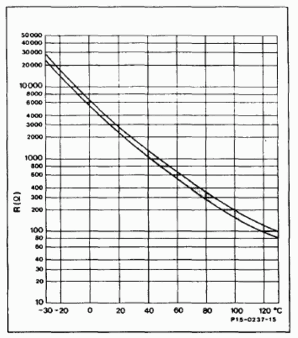
| Temperature | -30 | -20 | -10 | 0 | 10 | 20 | 30 | 40 | 50 | 60 | 70 | 80 | 90 | 100 | 110 | 120 |
|---|---|---|---|---|---|---|---|---|---|---|---|---|---|---|---|---|
| Voltage | 0.71 | 0.73 | 0.75 | 0.78 | 0.80 | 0.82 | 0.84 | 0.86 | 0.88 | 0.90 | 0.94 | 0.96 | 0.98 | 1.00 | 1.02 | 1.04 |
| ### Stock ECU wiring diagram |


Stock IAT sensor

| Temperature | -30 | -20 | -10 | 0 | 10 | 20 | 30 | 40 | 50 | 60 | 70 | 80 | 90 | 100 | 110 | 120 |
|---|---|---|---|---|---|---|---|---|---|---|---|---|---|---|---|---|
| Voltage | 0.71 | 0.73 | 0.75 | 0.78 | 0.80 | 0.82 | 0.84 | 0.86 | 0.88 | 0.90 | 0.94 | 0.96 | 0.98 | 1.00 | 1.02 | 1.04 |
MAP sensor pinout
Invent Jetronic ECU pinout
| 8 | 7 | 6 | 5 | 4 | 3 | 2 | 1 | |
| A | IDLE | INJ1 | INJ2 | INJ3 | INJ4 | INJ5 | INJ6 | X1** |
| B | +12V | CLT | TPS | AN | KLINE | EMUL | IDLE SW | FULL SW |
| C | GND | 5V OUT | IAT | MAP | LAMBDA | EXT | DH | AC* |
() - available in version 2.3 (*) - available in version 2.5
3-wire IAC valve
This valve contains two windings: one for opening and another for closing.
An external circuit is necessary to connect this valve. A MOSFET capable of handling over 5A of current and more than 55V of voltage is used (for example IRFZ44)
The dotted line represents the IAC case
Abbreviations
- MAP - absolute pressure sensor
- TPS - throttle position sensor
- IAT - sensor air temperature
- CLT - coolant temperature sensor
- DH - Hall sensor
- AFS - airflow sensor
Mercedes M102
First, remove the air filter. Next, detach the mechanical injectors along with the distributor.
The airflow sensor plate is no longer required. Remove it and secure the moving component beneath with a plastic strap.
Injector rail
To install the injectors, first insert them into the new fuel rail. Next, adjust the two metal brackets on the rail by bending them as needed, and drill a hole in each bracket for the screws that will secure it to the intake manifold.
Before drilling, ensure you take accurate measurements and verify that the injectors are fully seated in their housings.

Ensure to hermetically seal the start injector housing with a metal plate and RTV Silicone gasket. (Arexons Motorblack is recommended)
You can also use a rubber tube with the external diameter of the start injector housing and then bolt a screw onto it to hermetically seal it.

Please ensure to thoroughly inspect the EGR piping. Any air leaks in the circuit may result in idle performance issues.

Fuel lines and filter
Proceed with the installation of the new fuel lines.

The metal cylinder with three fittings serves as both a fuel filter and a pressure regulator, necessitating the removal of the old original unit.
- Connect the feeding line from the fuel pump to the "IN" fitting.
- Attach the return line, which goes back to the tank, directly to the unnamed central fitting.
- Connect the main line leading to the fuel rail to the "OUT" fitting.
Utilize the three black junctions included in the kit to connect the rubber line to the filter/pressure regulator, ensuring they are securely mounted.
Once the fuel lines are installed, cycle the ignition on and off 5-6 times without engaging the starter to build pressure in the fuel lines.
Thoroughly inspect for any potential leaks.
The fitting features a cone-shaped seal that tightens under fuel pressure. If you notice a leak, try gently moving the fitting back and forth. If it continues to leak, remove it and apply a small amount of oil to the sealing parts.
Idle valve
Clean the valve internals using carburetor cleaner and lubricate them with oil. Avoid using WD-40, as it is not a good lubricant. Bicycle chain lubricant is well suitable for this purpose.
MAP sensor
The precise placement of the MAP sensor is crucial for optimal engine performance. Please position the MAP sensor exactly as shown on the photo
Drill a 13mm hole for the sensor and an 8mm hole for the securing bolt. Apply grease to the drill tip to capture debris. It is recommended to clean the intake manifold thoroughly after drilling to ensure no metal debris remains.
Apply a sealant to fill the hole, ensuring an adequate amount of sealing paste is used due to the rough surface of the intake manifold.
Secure sensor with included screw. Apply sealant to the thread, to prevent air leaks and unscrewing.
Never install the sensor with the wires facing upwards to prevent water from running along the cable, which could lead to connector flooding and subsequent oxidation.
Secure the sensor using the screw. Apply sealant to the threads to prevent air leaks and ensure the sensor remains securely fastened.
Warning
Installing a MAP sensor in place of a cold start injector is strictly prohibited.

ECU and wiring
Warning
Disconnect the battery when servicing the electrical system. Reconnect the battery only when the engine needs to be started.
The ECU is designed to be dust and splash-resistant but is not suitable for continuous exposure to water or pressurized water. It is recommended to install it in a dry and secure location. Ensure that the ECU is not installed with the cable facing upwards, as this may allow water and moisture to enter the unit.
Warning
Wire colors may change without prior notice. If wires have text labels, use these labels to identify the purpose of each wire.
The wiring harness for 4-cylinder and 6-cylinder engines is standardized. For a 4-cylinder engine, the connections for the 5th and 6th cylinders will remain unused.
The optimal location for installing the ECU is adjacent to the stock unit. The stock ECU locations are as follows:
- W124: Under the hood, next to the battery
- W126: Front passenger footwell compartment
Extract the necessary wires from the new harness. Connect all new wires in parallel with the stock ECU unless otherwise specified.
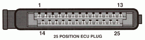
Connection to the 25pin ECU
- 1 - 12V
- 2 - GND
- 3 - IDLE (optional, read Idle Control section below)
- 5 - K-FULL
- 8 - Lambda - cut the wire to the stock ECU
- 13 - K-IDLE
- 21 - CLT
- 25 - AN
Connection to the 55pin ECU
- 6 - GND
- 9 - 12V
- 13 - Lambda - cut the wire to the stock ECU
- 16 - CLT
- 23 - IDLE (optional, read Idle Control section below)
- 27 - AN
- 46 - K-FULL
- 47 - K-IDLE
Idle control
The stock Mercedes IAC controller is functioning properly and can remain unchanged. If you wish to control the IAC valve using Invent ECU, disconnect the wire from the stock ECU and connect it to the IDLE w
Attention
Only a 2-wire idle valve is supported. For a 3-wire valve, an external circuit is required. For further details, please refer to the Additional Information section at the end of the document.
Lambda sensor
Attention
Ensure the lambda is disconnected from the stock ECU to prevent any interference.
How to install an aftermarket sensor
LPG
Connect the EXT wire to the gas supply valve and activate the LPG mode by EXT input in the settings. The ECU will then adjust to operate on gas fuel.
For carburetted LPG systems, it is unnecessary to disconnect the power from the gasoline injectors. Simply select the Turn off injection option, and the fuel supply will be interrupted by the signal from the EXT. Connect the EXT wire to the gas supply valve and activate the LPG mode by EXT input in the settings. The ECU will then adjust to operate on gas fuel.
Air conditioner
Connect the AC (or EXT) wire to the air conditioner clutch wire. This connection is essential for maintaining the idle RPM when the air conditioner is engaged.
K-Line
To connect the K-Line cable, you will need to prepare three wires: Typically, the Bluetooth interface is used to connect to the ECU. However, in rare instances where the Bluetooth connection proves unreliable, the K-Line can be utilized as an alternative.
To connect the K-Line cable, you need 3 wires:
- 12V
- Ground
- K-line
Pinout of the K-Line cable:
Pinout of the car OBD2 connector
Other wires
This manual does not mention certain additional wires, which are reserved for future use. Please ensure that any unused wires are isolated and concealed within the harness.
Additional info
Stock ECU pinout
- 1 - Main relay power (Yel)
- 2 - Ground (Brn)
- 3 - Idle speed control valve control (Red/Wht)
- 4 -
- 5 - Full load throttle (Gry/Yel)
- 6 - Speed sensor (Grn/Yel)
- 7 - Ground/Return for cool. sensor (Brn/Wht)-Coolant sensor return for MY 1988 California version
- 8 - Oxygen sensor input (Grn)
- 9 - Fuel pump relay A/T (Grn/Blu)
- 10 - Electro-hydraulic actuator control(Brn/Blk)
- 11 - Altitude sensor (Blu/Red)
- 12 - Electro-hydraulic actuator supply (Brn/Blk)
- 13 - Closed throttle (Brn/Yel)
- 14 -
- 15 - Check engine indicator (Red/Grn)
- 16 - Ignition switch (Vio)
- 17 - Air flow sensor Input (Blu/Wht)
- 18 - Air flow sensor reference (Blu/Grn)
- 19 - A/C compressor (Blu/Yel)
- 20 - Ground (Brn/Red)
- 21 - Coolant temperature sensor (Grn/Red)
- 22 -
- 23 - Diagnostic
- 24 - Deceleration micro-switch input (Gry/wht)
- 25 - TD signal (Grn/Yell)
- 1 - Supply Battery voltage
- 2 - Purge valve
- 3 - 02 sensor heater voltage
- 4 - Idle speed control valve (+)
- 5 - Intake Air temperature sensor
- 6 - Chassis ground
- 7 - Impulse readout, malfunction memory
- 8 -
- 9 - Supply voltage
- 10 - Deceleration fuel shut-off microswitch
- 11 - Start signal
- 12 -
- 13 - 02 sensor signal
- 14 - Intake air temperature sensor
- 15 -
- 16 - Coolant temperature sensor
- 17 -
- 18 - Diagnostic signal 02 sensor heater
- 19 - Ground ECU
- 20 - Start valve activation
- 21 -
- 22 -
- 23 - Idle speed control Valve (-)
- 24 - Check engine warning lamp
- 25 -
- 26 - Data exchange with EZL ECU
- 27 - RPM signal
- 28 - Selector lever position
- 29 - Speed signal
- 30 - Lambda output, on/off ratio
- 31 - Air flow sensor supply voltage
- 32 - 02 sensor wire shielding
- 33 -
- 34 - Air flow sensor ground
- 35 - Ground
- 36 -
- 37 - Electro hydraulic actuator (+)
- 38 - EGR valve
- 39 - Transmission shift point control
- 40 -
- 41 - Supply voltage
- 42 - Air pump control signal
- 43 -
- 44 -
- 45 - A/C compressor engagement signal
- 46 - Full load throttle signal
- 47 - Closed throttle signal
- 48 -
- 49 -
- 50 -
- 51 -
- 52 - Air flow sensor input signal
- 53 -
- 54 -
- 55 - Electro hydraulic actuator (-)
TSZ-h pinout
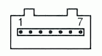
| Pin | Connection | Signal type | Wire color |
|---|---|---|---|
| 1 | Ignition coil connection 1 | Engine RPM | green |
| 2 | Ground | Power supply (-) | brown |
| 3 | Hall sensor connection 1/- | Power supply (-) | brown/white |
| 4 | Ignition coil connection 15 | Power supply (+) | black |
| 5 | Hall sensor connection 3/+ | Power supply (+) | red/black |
| 6 | Hall sensor connection 2/0 | Ignition timing | green/white |
| 7 | Digijet control unit connection 1 | Engine RPM | green |
Engine wiring harness

Engine temperature sensor
MAP sensor pinout
Invent Jetronic ECU pinout
| 8 | 7 | 6 | 5 | 4 | 3 | 2 | 1 | |
| A | IDLE | INJ1 | INJ2 | INJ3 | INJ4 | INJ5 | INJ6 | X1** |
| B | +12V | CLT | TPS | AN | KLINE | EMUL | IDLE SW | FULL SW |
| C | GND | 5V OUT | IAT | MAP | LAMBDA | EXT | DH | AC* |
() - available in version 2.3 (*) - available in version 2.5
3-wire IAC valve
This valve contains two windings: one for opening and another for closing.
An external circuit is necessary to connect this valve. A MOSFET capable of handling over 5A of current and more than 55V of voltage is used (for example IRFZ44)
The dotted line represents the IAC case
Abbreviations
- MAP - absolute pressure sensor
- TPS - throttle position sensor
- IAT - sensor air temperature
- CLT - coolant temperature sensor
- DH - Hall sensor
- AFS - airflow sensor
Mercedes M103
First, remove the air filter. Next, detach the mechanical injectors along with the distributor.
The airflow sensor plate is no longer required. Remove it and secure the moving component beneath with a plastic strap.
Injector rail
To properly install the injectors, it is necessary to cut a part of the intake manifold, as shown in the photo below.

Apply engine sealant to install the injector sleeves.

Insert the injectors first into the fuel rail, followed by the manifold.

Bend the metal brackets of the rail and drill a hole in each bracket to insert the screw that will secure it to the intake manifold.
Fuel lines and filter
Proceed with the installation of the new fuel lines.
The metal cylinder with three fittings serves as both a fuel filter and a pressure regulator, necessitating the removal of the old original unit.
- Connect the feeding line from the fuel pump to the "IN" fitting.
- Attach the return line, which goes back to the tank, directly to the unnamed central fitting.
- Connect the main line leading to the fuel rail to the "OUT" fitting.
Utilize the three black junctions included in the kit to connect the rubber line to the filter/pressure regulator, ensuring they are securely mounted.
Once the fuel lines are installed, cycle the ignition on and off 5-6 times without engaging the starter to build pressure in the fuel lines.
Thoroughly inspect for any potential leaks.
The fitting features a cone-shaped seal that tightens under fuel pressure. If you notice a leak, try gently moving the fitting back and forth. If it continues to leak, remove it and apply a small amount of oil to the sealing parts.
Idle air control valve (ICV)
The existing air supply configuration from the ICV is not suitable for use.
Install a new air supply fitting beneath the throttle and connect the air supply hose to the idle valve.


If your engine is equipped with the EGR system (U.S. version), there is no need to install the fitting. Simply block the EGR piping and use the EGR line to supply air from the ICV.
Clean the valve internals using carburetor cleaner and lubricate them with oil. Avoid using WD-40, as it is not a good lubricant. Bicycle chain lubricant is well suitable for this purpose.
MAP
The precise placement of the MAP sensor is crucial for optimal engine performance. Please position the MAP sensor exactly as shown on the photo
Drill a 13mm hole for the sensor and an 8mm hole for the securing bolt. Apply grease to the drill tip to capture debris. It is recommended to clean the intake manifold thoroughly after drilling to ensure no metal debris remains.
Apply a sealant to fill the hole, ensuring an adequate amount of sealing paste is used due to the rough surface of the intake manifold.
Secure sensor with included screw. Apply sealant to the thread, to prevent air leaks and unscrewing.
Never install the sensor with the wires facing upwards to prevent water from running along the cable, which could lead to connector flooding and subsequent oxidation.
Secure the sensor using the screw. Apply sealant to the threads to prevent air leaks and ensure the sensor remains securely fastened.
Warning
Installing a MAP sensor in place of a cold start injector is strictly prohibited.


ECU and wiring
Warning
Disconnect the battery when servicing the electrical system. Reconnect the battery only when the engine needs to be started.
The ECU is designed to be dust and splash-resistant but is not suitable for continuous exposure to water or pressurized water. It is recommended to install it in a dry and secure location. Ensure that the ECU is not installed with the cable facing upwards, as this may allow water and moisture to enter the unit.
Warning
Wire colors may change without prior notice. If wires have text labels, use these labels to identify the purpose of each wire.
The wiring harness for 4-cylinder and 6-cylinder engines is standardized. For a 4-cylinder engine, the connections for the 5th and 6th cylinders will remain unused.
The optimal location for installing the ECU is adjacent to the stock unit. The stock ECU locations are as follows:
- W124: Under the hood, next to the battery
- W126: Front passenger footwell compartment
Extract the necessary wires from the new harness. Connect all new wires in parallel with the stock ECU unless otherwise specified.
Connection to the 25pin ECU
- 1 - 12V
- 2 - GND
- 3 - IDLE (optional, read Idle Control section below)
- 5 - K-FULL
- 8 - Lambda - cut the wire to the stock ECU
- 13 - K-IDLE
- 21 - CLT
- 25 - AN
Connection to the 55pin ECU
- 6 - GND
- 9 - 12V
- 13 - Lambda - cut the wire to the stock ECU
- 16 - CLT
- 23 - IDLE (optional, read Idle Control section below)
- 27 - AN
- 46 - K-FULL
- 47 - K-IDLE
Idle control
The stock Mercedes IAC controller is functioning properly and can remain unchanged. If you wish to control the IAC valve using Invent ECU, disconnect the wire from the stock ECU and connect it to the IDLE w
Attention
Only a 2-wire idle valve is supported. For a 3-wire valve, an external circuit is required. For further details, please refer to the Additional Information section at the end of the document.
Lambda sensor
Attention
Ensure the lambda is disconnected from the stock ECU to prevent any interference.
How to install an aftermarket sensor
LPG
Connect the EXT wire to the gas supply valve and activate the LPG mode by EXT input in the settings. The ECU will then adjust to operate on gas fuel.
For carburetted LPG systems, it is unnecessary to disconnect the power from the gasoline injectors. Simply select the Turn off injection option, and the fuel supply will be interrupted by the signal from the EXT. Connect the EXT wire to the gas supply valve and activate the LPG mode by EXT input in the settings. The ECU will then adjust to operate on gas fuel.
Air conditioner
Connect the AC (or EXT) wire to the air conditioner clutch wire. This connection is essential for maintaining the idle RPM when the air conditioner is engaged.
K-Line
To connect the K-Line cable, you will need to prepare three wires: Typically, the Bluetooth interface is used to connect to the ECU. However, in rare instances where the Bluetooth connection proves unreliable, the K-Line can be utilized as an alternative.
To connect the K-Line cable, you need 3 wires:
- 12V
- Ground
- K-line
Pinout of the K-Line cable:
Pinout of the car OBD2 connector
Other wires
This manual does not mention certain additional wires, which are reserved for future use. Please ensure that any unused wires are isolated and concealed within the harness.
Additional info
Stock ECU pinout
- 1 - Main relay power (Yel)
- 2 - Ground (Brn)
- 3 - Idle speed control valve control (Red/Wht)
- 4 -
- 5 - Full load throttle (Gry/Yel)
- 6 - Speed sensor (Grn/Yel)
- 7 - Ground/Return for cool. sensor (Brn/Wht)-Coolant sensor return for MY 1988 California version
- 8 - Oxygen sensor input (Grn)
- 9 - Fuel pump relay A/T (Grn/Blu)
- 10 - Electro-hydraulic actuator control(Brn/Blk)
- 11 - Altitude sensor (Blu/Red)
- 12 - Electro-hydraulic actuator supply (Brn/Blk)
- 13 - Closed throttle (Brn/Yel)
- 14 -
- 15 - Check engine indicator (Red/Grn)
- 16 - Ignition switch (Vio)
- 17 - Air flow sensor Input (Blu/Wht)
- 18 - Air flow sensor reference (Blu/Grn)
- 19 - A/C compressor (Blu/Yel)
- 20 - Ground (Brn/Red)
- 21 - Coolant temperature sensor (Grn/Red)
- 22 -
- 23 - Diagnostic
- 24 - Deceleration micro-switch input (Gry/wht)
- 25 - TD signal (Grn/Yell)
- 1 - Supply Battery voltage
- 2 - Purge valve
- 3 - 02 sensor heater voltage
- 4 - Idle speed control valve (+)
- 5 - Intake Air temperature sensor
- 6 - Chassis ground
- 7 - Impulse readout, malfunction memory
- 8 -
- 9 - Supply voltage
- 10 - Deceleration fuel shut-off microswitch
- 11 - Start signal
- 12 -
- 13 - 02 sensor signal
- 14 - Intake air temperature sensor
- 15 -
- 16 - Coolant temperature sensor
- 17 -
- 18 - Diagnostic signal 02 sensor heater
- 19 - Ground ECU
- 20 - Start valve activation
- 21 -
- 22 -
- 23 - Idle speed control Valve (-)
- 24 - Check engine warning lamp
- 25 -
- 26 - Data exchange with EZL ECU
- 27 - RPM signal
- 28 - Selector lever position
- 29 - Speed signal
- 30 - Lambda output, on/off ratio
- 31 - Air flow sensor supply voltage
- 32 - 02 sensor wire shielding
- 33 -
- 34 - Air flow sensor ground
- 35 - Ground
- 36 -
- 37 - Electro hydraulic actuator (+)
- 38 - EGR valve
- 39 - Transmission shift point control
- 40 -
- 41 - Supply voltage
- 42 - Air pump control signal
- 43 -
- 44 -
- 45 - A/C compressor engagement signal
- 46 - Full load throttle signal
- 47 - Closed throttle signal
- 48 -
- 49 -
- 50 -
- 51 -
- 52 - Air flow sensor input signal
- 53 -
- 54 -
- 55 - Electro hydraulic actuator (-)
TSZ-h pinout
| Pin | Connection | Signal type | Wire color |
|---|---|---|---|
| 1 | Ignition coil connection 1 | Engine RPM | green |
| 2 | Ground | Power supply (-) | brown |
| 3 | Hall sensor connection 1/- | Power supply (-) | brown/white |
| 4 | Ignition coil connection 15 | Power supply (+) | black |
| 5 | Hall sensor connection 3/+ | Power supply (+) | red/black |
| 6 | Hall sensor connection 2/0 | Ignition timing | green/white |
| 7 | Digijet control unit connection 1 | Engine RPM | green |
MAP sensor pinout
Invent Jetronic ECU pinout
| 8 | 7 | 6 | 5 | 4 | 3 | 2 | 1 | |
| A | IDLE | INJ1 | INJ2 | INJ3 | INJ4 | INJ5 | INJ6 | X1** |
| B | +12V | CLT | TPS | AN | KLINE | EMUL | IDLE SW | FULL SW |
| C | GND | 5V OUT | IAT | MAP | LAMBDA | EXT | DH | AC* |
() - available in version 2.3 (*) - available in version 2.5
3-wire IAC valve
This valve contains two windings: one for opening and another for closing.
An external circuit is necessary to connect this valve. A MOSFET capable of handling over 5A of current and more than 55V of voltage is used (for example IRFZ44)
The dotted line represents the IAC case
Abbreviations
- MAP - absolute pressure sensor
- TPS - throttle position sensor
- IAT - sensor air temperature
- CLT - coolant temperature sensor
- DH - Hall sensor
- AFS - airflow sensor
Mercedes V8
First, remove the air filter. Next, detach the mechanical injectors along with the injection distributor. Finally, remove the injector air feeding ducts.

The airflow sensor plate is no longer required. Remove it and secure the moving component beneath with a plastic strap.

Injector rails
Install sleeves onto the injectors.

Insert the injectors first into the fuel rail, followed by the manifold.
Bend the metal brackets of the rail and drill a hole in each bracket to insert the screw that will secure it to the intake manifold.

Idle air control valve (ICV)
The existing air supply configuration from the ICV is not suitable for use.
Block the EGR piping. Use the previously removed ICV pipes to create a new connection between the ICV and the EGR air feed.


Clean the ICV valve internals using carburetor cleaner and lubricate them with oil. Avoid using WD-40, as it is not a good lubricant. Bicycle chain lubricant is well suitable for this purpose.
MAP
The precise placement of the MAP sensor is crucial for optimal engine performance. Please position the MAP sensor fitting exactly as shown on the photo
Drill a hole for the fitting in the manifold. Apply grease to the drill tip to capture debris. It is recommended to clean the intake manifold thoroughly after drilling to ensure no metal debris remains.


ECU and wiring
Warning
Disconnect the battery when servicing the electrical system. Reconnect the battery only when the engine needs to be started.
The ECU is designed to be dust and splash-resistant but is not suitable for continuous exposure to water or pressurized water. It is recommended to install it in a dry and secure location. Ensure that the ECU is not installed with the cable facing upwards, as this may allow water and moisture to enter the unit.
Warning
Wire colors may change without prior notice. If wires have text labels, use these labels to identify the purpose of each wire.
The wiring harness for 4-cylinder and 6-cylinder engines is standardized. For a 4-cylinder engine, the connections for the 5th and 6th cylinders will remain unused.
The optimal location for installing the ECU is adjacent to the stock unit. The stock ECU locations are as follows:
- W124: Under the hood, next to the battery
- W126: Front passenger footwell compartment
Extract the necessary wires from the new harness. Connect all new wires in parallel with the stock ECU unless otherwise specified.
Connection to the 25pin ECU
- 1 - 12V
- 2 - GND
- 3 - IDLE (optional, read Idle Control section below)
- 5 - K-FULL
- 8 - Lambda - cut the wire to the stock ECU
- 13 - K-IDLE
- 21 - CLT
- 25 - AN
Connection to the 55pin ECU
- 6 - GND
- 9 - 12V
- 13 - Lambda - cut the wire to the stock ECU
- 16 - CLT
- 23 - IDLE (optional, read Idle Control section below)
- 27 - AN
- 46 - K-FULL
- 47 - K-IDLE
Idle control
The stock Mercedes IAC controller is functioning properly and can remain unchanged. If you wish to control the IAC valve using Invent ECU, disconnect the wire from the stock ECU and connect it to the IDLE w
Attention
Only a 2-wire idle valve is supported. For a 3-wire valve, an external circuit is required. For further details, please refer to the Additional Information section at the end of the document.
Lambda sensor
Attention
Ensure the lambda is disconnected from the stock ECU to prevent any interference.
How to install an aftermarket sensor
LPG
Connect the EXT wire to the gas supply valve and activate the LPG mode by EXT input in the settings. The ECU will then adjust to operate on gas fuel.
For carburetted LPG systems, it is unnecessary to disconnect the power from the gasoline injectors. Simply select the Turn off injection option, and the fuel supply will be interrupted by the signal from the EXT. Connect the EXT wire to the gas supply valve and activate the LPG mode by EXT input in the settings. The ECU will then adjust to operate on gas fuel.
Air conditioner
Connect the AC (or EXT) wire to the air conditioner clutch wire. This connection is essential for maintaining the idle RPM when the air conditioner is engaged.
K-Line
To connect the K-Line cable, you will need to prepare three wires: Typically, the Bluetooth interface is used to connect to the ECU. However, in rare instances where the Bluetooth connection proves unreliable, the K-Line can be utilized as an alternative.
To connect the K-Line cable, you need 3 wires:
- 12V
- Ground
- K-line
Pinout of the K-Line cable:
Pinout of the car OBD2 connector
Other wires
This manual does not mention certain additional wires, which are reserved for future use. Please ensure that any unused wires are isolated and concealed within the harness.
Additional info
Stock ECU pinout
- 1 - Main relay power (Yel)
- 2 - Ground (Brn)
- 3 - Idle speed control valve control (Red/Wht)
- 4 -
- 5 - Full load throttle (Gry/Yel)
- 6 - Speed sensor (Grn/Yel)
- 7 - Ground/Return for cool. sensor (Brn/Wht)-Coolant sensor return for MY 1988 California version
- 8 - Oxygen sensor input (Grn)
- 9 - Fuel pump relay A/T (Grn/Blu)
- 10 - Electro-hydraulic actuator control(Brn/Blk)
- 11 - Altitude sensor (Blu/Red)
- 12 - Electro-hydraulic actuator supply (Brn/Blk)
- 13 - Closed throttle (Brn/Yel)
- 14 -
- 15 - Check engine indicator (Red/Grn)
- 16 - Ignition switch (Vio)
- 17 - Air flow sensor Input (Blu/Wht)
- 18 - Air flow sensor reference (Blu/Grn)
- 19 - A/C compressor (Blu/Yel)
- 20 - Ground (Brn/Red)
- 21 - Coolant temperature sensor (Grn/Red)
- 22 -
- 23 - Diagnostic
- 24 - Deceleration micro-switch input (Gry/wht)
- 25 - TD signal (Grn/Yell)
- 1 - Supply Battery voltage
- 2 - Purge valve
- 3 - 02 sensor heater voltage
- 4 - Idle speed control valve (+)
- 5 - Intake Air temperature sensor
- 6 - Chassis ground
- 7 - Impulse readout, malfunction memory
- 8 -
- 9 - Supply voltage
- 10 - Deceleration fuel shut-off microswitch
- 11 - Start signal
- 12 -
- 13 - 02 sensor signal
- 14 - Intake air temperature sensor
- 15 -
- 16 - Coolant temperature sensor
- 17 -
- 18 - Diagnostic signal 02 sensor heater
- 19 - Ground ECU
- 20 - Start valve activation
- 21 -
- 22 -
- 23 - Idle speed control Valve (-)
- 24 - Check engine warning lamp
- 25 -
- 26 - Data exchange with EZL ECU
- 27 - RPM signal
- 28 - Selector lever position
- 29 - Speed signal
- 30 - Lambda output, on/off ratio
- 31 - Air flow sensor supply voltage
- 32 - 02 sensor wire shielding
- 33 -
- 34 - Air flow sensor ground
- 35 - Ground
- 36 -
- 37 - Electro hydraulic actuator (+)
- 38 - EGR valve
- 39 - Transmission shift point control
- 40 -
- 41 - Supply voltage
- 42 - Air pump control signal
- 43 -
- 44 -
- 45 - A/C compressor engagement signal
- 46 - Full load throttle signal
- 47 - Closed throttle signal
- 48 -
- 49 -
- 50 -
- 51 -
- 52 - Air flow sensor input signal
- 53 -
- 54 -
- 55 - Electro hydraulic actuator (-)
TSZ-h pinout
| Pin | Connection | Signal type | Wire color |
|---|---|---|---|
| 1 | Ignition coil connection 1 | Engine RPM | green |
| 2 | Ground | Power supply (-) | brown |
| 3 | Hall sensor connection 1/- | Power supply (-) | brown/white |
| 4 | Ignition coil connection 15 | Power supply (+) | black |
| 5 | Hall sensor connection 3/+ | Power supply (+) | red/black |
| 6 | Hall sensor connection 2/0 | Ignition timing | green/white |
| 7 | Digijet control unit connection 1 | Engine RPM | green |
MAP sensor pinout
Invent Jetronic ECU pinout
| 8 | 7 | 6 | 5 | 4 | 3 | 2 | 1 | |
| A | IDLE | INJ1 | INJ2 | INJ3 | INJ4 | INJ5 | INJ6 | X1** |
| B | +12V | CLT | TPS | AN | KLINE | EMUL | IDLE SW | FULL SW |
| C | GND | 5V OUT | IAT | MAP | LAMBDA | EXT | DH | AC* |
() - available in version 2.3 (*) - available in version 2.5
3-wire IAC valve
This valve contains two windings: one for opening and another for closing.
An external circuit is necessary to connect this valve. A MOSFET capable of handling over 5A of current and more than 55V of voltage is used (for example IRFZ44)
The dotted line represents the IAC case
Abbreviations
- MAP - absolute pressure sensor
- TPS - throttle position sensor
- IAT - sensor air temperature
- CLT - coolant temperature sensor
- DH - Hall sensor
- AFS - airflow sensor
Trip computer
Pinout
- 12v - 12V from the battery
- gnd - ground
- dim - dimmer
- btn - button
- spd - speed sensor
- kl - K-line direct to the ECU
Info
The display activates when there is activity on the k-line. As a result, you should not connect other devices to this line or link this wire to the on-board network. If you do, the display will not turn off when the ignition is switched off. The display will remain active if the KLINE cable is connected to the car.
Warning
The K-Line wire connecting the display to the ECU should be routed away from the high-voltage coil and associated wiring.
Installation
Disassemble the dashboard (the photo shows a dashboard from an A6 C4).

cut 5mm here

insert the display

display should flush into the case

secure PCB and wires with a sealant or glue

Cut the plastic cap

Install the red filter instead (first, remove protective film from both sides)


Connection to Audi 100 (а6с4)
Red connector:
- 7 - speedometer
- 10 - ground
- 14 - +12v
- 17 - dimmer
Green connector:
- 2 (was not used) - K-line
- 8 (was not used) - button
Connect a wire from pin 2 of the green connector to the K-line of the Invent ECU.
Connection to Audi 100 C3 before restyling
Black connector T26:
- 2 - speedometer out
- 10 - ground
- 1 - +12v
- 5 - dimmer

Remove the protective film from the display.
Place the black sticker mask on top.

Then, assemble the dashboard
Button
If the wiper switch lacks a stock button, you can install a pushbutton instead.

For a 4-pin pushbutton, solder the wires diagonally to pins 1 and 3. Connect the first wire to the green connector at pin 2 of the dashboard, and the second wire to the ground. It is advisable to install the button into the wiper switch and secure it with glue or sealant.


The result

Dashboard pinout Audi 100 (а6с4)

Dashboard pinout Audi 100 C3 restyling
Basic dashboard (without additional gauges)
Black connector T26:
- 1 +12 V for clock – red - blue
- 2 speedometer signal – white-blue
- 3 fuel level – purple - black
- 4 speed sensor signal from gearbox – brown - red
- 5 dashboard backlight – gray - blue
- 6 high beam lamp – blue - white
- 7 parking brake lamp – gray - yellow
- 8 hazard lights lamp – blue - green
- 10 ground – brown
- 11 +10 V – black - blue
- 12 turn signal right – black - green
- 15 +12 V to the backlight regulator – gray - green
- 25 turn signal left – black - white
- 26 from hazard lihts – brown - white
Ignition control
The EMUL wire is utilized to control the ignition amplifier. It should be connected to the signal wire of the ignition amplifier by cutting the existing wire.
Setup:
- Turn on Parameters - Main - Ignition Control.
- Select Active level: 5 volts
- Set Zero Angle Correction = 0
- Reduce by half the parameter Idle - PID Settings - Kp

Set up the distributor with a strobe light:
- Start the engine and allow it to warm up.
- Activate Diagnostics - Test - Fixed Angle 0. The engine may run unevenly, ensure it does not stall.
- Use the stroboscope to locate the zero degree mark. For enhanced visibility, consider marking it with toothpaste or a white marker.
- Adjust the Zero Angle Correction parameter to align the mark. Ensure Autosave is enabled.
- Once adjustments are complete, switch off the ignition for 10 seconds.
For more information check those forum threads: - For Audi/Volkswagen - For Merecedes
Other sensors
Separate CLT sensor
If you encounter issues with the OEM engine temperature sensor, such as fluctuating readings or a missing or damaged OEM ECU, consider connecting an independent temperature sensor.
It is recommended to use a 2-wire sensor from an injection engine, with a resistance of 2-3 kΩ at 20°C.

Connect the SGND wire of the new sensor in parallel with the GND wire of the MAP sensor

Enable the manual mode and separate sensor options

If calibration of the sensor readings is required, please follow these steps:
- Click the calculator icon adjacent to the table.
- Set the sensor voltage at three specific reference points:
- 0°C (temperature of ice water)
- Room temperature (approximately 20°C)
- 100°C (boiling point of water)

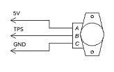
TPS sensor
You can use a modern throttle position sensor (TPS) instead of the original throttle switches. The 5V power supply and ground must be connected from the MAP.
Universal lambda sensor
If you do not have a lambda probe or the sensor is faulty, you should install a universal Bosch sensor 0258986507 or 0258006537. It is more reliable than the original 3-wire sensor.
The standard lambda probe has 3 wires: ECU signal, ECU ground, heater +12. It does not have a heater ground wire because the exhaust pipe is used as ground.
The new lambda sensor has 2 separate heater wires, and the heater itself is not connected to the sensor housing. This is a more reliable design.
Wiring diagram:
- white wires - to the lambda heater connector or to the fuel pump. One of them is the power supply, the other is the ground. Polarity does not matter.
- Black - signal to Invent Jetronic
- Gray - ground to Invent Jetronic (do not connect the ground elsewhere)
Replacement MAP sensor
If the MAP sensor on a naturally aspirated engine has failed, you can purchase the 120kpa sensor from our website or use the following part numbers as substitutes:
- Bosch 0261230217
- Bosch 0261230299
In the event of a turbo-MAP failure, there are no direct substitutes available. You can purchase the 400kpa sensor from our website.
Setting up
Software
Introduction
The software bundle includes three components:
1. Invent Commander
The Windows application for managing Invent Jetronic ECU allows you to handle calibrations, update firmware, and record log files.
2. Firmware
This program runs in the ECU and performs complex measurements and calculations to control fuel injectors, the idle valve, and other devices. It functions like the ECU's operating system.
The firmware can be updated to provide improvements and bug fixes.
Calibrations are necessary for the firmware to operate.
3. Calibrations
This is a set of options and tables.
It instructs the firmware on how to operate with a specific engine, describing the engine's characteristics, sensors, valves, injectors, and more.
Commander overview

Connection to the ECU
Bluetooth
Bluetooth is the preferred method for connecting to the ECU. Follow these steps to connect to the ECU's Bluetooth interface:
- Pair with the 'Jetronic' device using the PIN code '0000'.
- Navigate to Start > Settings > Devices > Bluetooth & other devices.
- Scroll down to Related settings and select More Bluetooth options.

- Go to the COM Ports tab to see the assigned OUTGOING COM port.
- Use this port for communication.

Info
When the ignition is turned off, the connection is lost, but the commander remains in the Searching state and does not detect this change. To reconnect, you must manually toggle the connection. This is the limitation of the Windows OS.
K-Line
Utilize the K-Line connection if you encounter issues with Bluetooth, as it is primarily used for interfacing with the trip computer. Additionally, it is advisable to update the firmware using a K-Line cable to prevent the vehicle from becoming immobile due to an update failure.
Connection procedure
Follow these steps to connect to the ECU:
- Select the USB COM port in the commander and press "ON."
- If using Bluetooth, wait a few seconds for the connection to establish. The K-Line connection is instantaneous.
- Upon successful connection, the commander will read all calibrations from the ECU.
Warning
If you encounter a Commander version don't correspond to firmware version error, disconnect immediately and download the correct Commander version from our website. Using the incorrect version of Commander can disrupt calibrations and prevent the engine from starting.
Working with calibrations
Calibrations are stored in the ECU, and without them, the ECU cannot start the engine.
If you modify the calibrations, you must update them in the ECU.
Calibrations can also be saved in files. It is advisable to save the calibrations to a file after making any changes.
Info
The Commander saves a record of all changes to the ECU in the history folder. If an accident occurs, you can restore calibrations from the history.
How to load calibrations from the file to the ECU
- Connect to the ECU.
- Select Load calibrations from the file and open the desired file.
- Make any necessary changes.
- Select Save calibrations to the ECU.
- Wait for the writing process to complete.
How to change calibrations in the ECU
- Connect to the ECU.
- Verify that calibrations are successfully read from the ECU.
- Select the Autosave checkbox to apply all changes immediately.
- Modify the calibrations as needed.
- Be aware that the Autosave checkbox will blink red while saving to the ECU.
- Once finished, save the calibrations to a file.
Log recording
Log files are useful for engine tuning and troubleshooting. They are stored in the Logs folder.
How to record a log
- Connect to the ECU.
- Press the Record log button. It will stay pressed, and the timer will start running.
- When finished, press the Record log button again to save the log and stop the time
Log viewing
How to view a log
- Click Open log file button and select the desired log file.
- Click View log chart to open a window displaying the log chart.
- In the log chart, select the parameters you wish to view.
- Click on the chart to set active point in the commander tables.
Navigating the Log Chart
- Use the mouse wheel to zoom in and out.
- Click the left mouse button to set the current position in the log.
- Drag with the right mouse button to pan across the chart.
- Press the Up/Down arrow keys to zoom.
- Press the Left/Right arrow keys to pan.
- Hold Ctrl and press the Left/Right arrow keys to move the marker step by step.
Firmware update
Danger
If a failure occurs, you will not be able to start the engine. Do not attempt this if you don't have a K-Line cable nearby.
Update procedure
- Turn on the ignition and connect to the ECU.
- IMPORTANT: Read the calibrations from the ECU and save them to a file.
- Open the Parameters - Firmware tab.
- Click Update firmware and choose the firmware file.
- Wait for the upload to complete.
- Reconnect to the ECU.
- Open the calibrations you saved earlier and upload them to the ECU.
- Wait 10 seconds after completion, then turn off the ignition.
If update fails
You will no longer be able to connect to the ECU, as it will display an indefinite Searching status. This is expected due to the absence of valid firmware.
Rest assured, the ECU is designed to withstand firmware updates without being damaged. As long as there is power, a connection, and the CPU is operational, you can re-upload the firmware.
- Disable any battery-saving modes on your laptop.
- Close all other applications, including messaging apps.
- Connect to the ECU; it will show a Searching status.
- Disregard this status, select Update firmware, and proceed as usual.
If nothing helps
As a final measure, ensure you have a K-Line cable equipped with an FTDI chip, as other chips may be unreliable.
Instructions:
- Turn the ignition OFF.
- Select the appropriate COM port, but don't press "Connect" button
- Click Update Firmware and choose the firmware file.
- Wait for the Searching message, then turn the ignition ON immediately
- The upload process should start.
If the upload does not start, consider the following troubleshooting steps:
- Verify the 12V power supply to the ECU.
- Ensure the KLine cable lamp is illuminated when the cable is connected to the ECU but not to the USB.
- Confirm the correct COM port is selected.
- Try using a different laptop.
- Try using a different K-Line cable.
- Try disconnecting battery terminal instead of turning off the ignition.
First start and setup
Before you begin, make sure you have:
- The latest version of Invent Commander software
- A working cable for connecting to the ECU (electronic control unit)
- A stable internet connection to download the program
The ECU is the “brain” of your engine, controlling all fuel delivery and ignition processes. Proper configuration is critical for safe engine operation.
- Downloading the program
Download the [Invent Commander] program from our website:
http://www.invent-labs.com/jetronic/files
Why this is important: Using unofficial versions may result in incorrect operation or even damage to the engine.
-
Connecting to the ECU
-
Launch Invent Commander.
- Check that the cable is securely connected
- Click “Connect to ECU”
- Wait for the loading indicator to appear - this means that the program is reading the current settings from the ECU
All calibrations (engine settings) should be automatically downloaded from the ECU to the program. You will see the fields filled in with the engine parameters.
If the loading indicator does not appear, or a connection error appears → check the cable, drivers, and COM port number
!!! warning “Warning”
If the message “incorrect version” appears, immediately disconnect from the ECU and do not continue. Download the correct version of Invent Commander from our website.
Using the wrong version can damage the calibration and the engine will not start.
- Using standard calibrations
Calibration is a set of settings that determine how your engine works: how much fuel to supply, how to regulate idle speed, etc.
The package already includes basic calibrations for your engine type. These are “universal” settings that are suitable for most engines of this type.
Always start with the basic calibrations. After successful startup and configuration, you can refine them for the specific characteristics of your engine.
Initial configuration
Before starting the engine, you need to configure the basic system parameters.
Parameters - General

- Basic parameters - set the engine type, displacement, and maximum RPM. Warning! Exceeding the maximum RPM will result in connecting rod failure.
- Injection settings - specify the injectors you have installed
- Fuel pressure regulator - select 4 bar, no vacuum
- Lambda control and adaptation - turn off (we will configure later)
- LPG mode - turn off (if you use LPG - we will configure later)
- Ignition control - turn on if you use Invent ignition control. However, we recommend performing the first start with the standard ignition system.
- ECU name - Enter a meaningful name, such as “Audi AAR” or “M103 3.0”
- Bluetooth PIN - we recommend leaving the default 0000. But for added security, you can change the PIN code.
!!!warning “Warning” If you have changed the Bluetooth PIN code and forgotten it, you will only be able to connect via the K-Line cable.
Parameters - Sensors
Sensors inform the ECU about temperature, pressure, accelerator pedal position, etc.

General options
- Broadband lambda: Usually, a regular lambda is used, and this option should be disabled. If you have installed a broadband lambda, enable it and set the calibration (you can find it in the broadband lambda manual).
- TPS: Normally, limit switches are used, and this option should be disabled. If you have installed a TPS, enable it and set the calibration for the 0% and 100% positions.
- IAT sensor heating compensation: enabled for atmospheric engines and disabled for turbo engines.
Temperature sensors
Check the engine and air temperatures. When the engine is cold, both temperatures should be approximately the same (the difference should not exceed 3-5°C).
If the temperatures differ significantly or show unrealistic values
-
Check the sensor pull-up parameters:
-
To the standard ECU - if the sensor is connected in parallel to the standard system. For example, engine temperature.
-
Separate sensor - if the sensor is separate. For example, IAT built into the DAT sensor.
-
Check the sensor voltage on the sensor calibration tab:
When connected to the “Standard ECU”:
- 0V - Sensor not connected, short circuit of the signal wire to ground, break in the signal wire from the standard ECU, damage to the standard ECU
- 5V - no negative on the stock sensor
When connected to a “separate sensor”:
- 0V - short circuit of the signal wire to ground
-
5V - no connection to the sensor, signal wire break, no negative on the sensor
-
Check the sensor calibration:
Try changing different calibrations. If nothing is displayed correctly, switch to manual mode and perform your own calibration.
For manual sensor calibration, you need to enter 3 arbitrary temperature-voltage pairs.
It is convenient to use the following control points: - 0°C: immerse the sensor in ice water and record the voltage readings. - Room temperature: record the voltage readings when the sensor is at room temperature. - 100°C: immerse the sensor in a boiling kettle and record the voltage readings.

Throttle limit switches
The status of the switches is displayed here

These switches show the ECU the position of the accelerator pedal. It is extremely important that these switches work correctly. If they malfunction, the engine may:
- Display a DAT error
- Start poorly or not start at all
- Run unsteadily at idle speed
Idle switch
- Make sure that the Idle indicator turns on when the pedal is released.
- Make sure that the Idle indicator turns off when the throttle just starts to move.
- Make sure that the Idle indicator remains off until the pedal is 100% depressed.
- Make sure that the Idle indicator turns on reliably every time you release the pedal.
Check several times at different pedal speeds.
Possible problems:
- Dirty throttle cable, preventing the throttle from returning to the closed position
- Incorrectly adjusted throttle stop, preventing the throttle from returning to the closed position
Full throttle switch
Press the pedal all the way down and look at the full throttle indicator.
- Atmospheric engines: the indicator should come on at approximately 90% of the pedal travel.
- Audi turbo engines: the indicator should come on at 55% of the pedal travel.
!!!feature “Cylinder drying mode” If the full load sensor is triggered while the starter is running, the fuel supply is interrupted. This helps to “dry” flooded spark plugs and start the engine.
If the sensors work in reverse
Symptoms:
- Full load mode is active when the pedal is released
- Idle mode is active when the pedal is pressed
Solution:
- In the settings, select “Manual engine settings”
- Find the “Terminal Inversion” option
- Change its status to the correct sensor operation
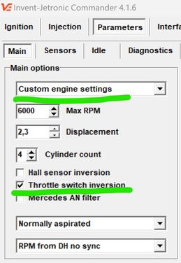
Starting the engine
Now you can try to start the engine.
Before starting, make sure that:
- All settings are saved
- The fuel pump is working
- There is pressure in the fuel system
- The battery is charged
- The ECU is connected and the program shows the connection
If the engine does not start:
1: Check the engine speed
- Turn the engine with the starter
- The ECU should show the speed (usually 150-200 rpm when turning)
- If there is no speed, check the speed signal connection (DH or AN, depending on the engine type)
2: Check the injection time
- The injection time should be displayed while the starter is running (for example, 3-8 ms)
- If there is no injection time:
- While cranking with the starter, the full load sensor must be OFF. If it is on, the engine is in “dry” mode. Correct the sensor settings.
- Re-load the basic calibrations.
3: Check the mechanical part
- Fuel pressure in the rail (should be 4 bar)
- Presence of spark on the spark plugs
- Are the spark plugs dry? If they are wet, dry them over an open flame.
- Correct connection of high-voltage wires
After successful start-up
Allow the engine to warm up to operating temperature (80-90°C).
If the RPM jumps from 1000 to 2000 and back again, use the Manual slider on the Parameters > Idle tab to temporarily stabilize the RPM until the engine warms up.
Lambda probe
A lambda probe is a sensor that monitors the quality of the air-fuel mixture.
Initial state (cold sensor)
When the engine is cold, the lambda sensor voltage is 0.45-0.55V. This is normal - the sensor has not yet warmed up to operating temperature.
Troubleshooting
Only diagnose the sensor after the engine has warmed up to operating temperature.
A properly functioning lambda sensor shows a voltage in the range of 0.1-0.2V to 0.7-1.2V, which fluctuates constantly:
- Low voltage (0.1-0.3V) = lean mixture (not enough fuel)
- High voltage (0.7-1.0V) = rich mixture (too much fuel)
If the voltage is 0V:
- Short circuit of the signal wire to ground
- Check the integrity of the wiring
- Check the resistance of the lambda sensor (should be 2-14 kOhm between signal contacts)
If the voltage remains within 0.45-0.55 V:
Check the connections:
- Signal wire is connected correctly
- Sensor ground is connected to the body
Check the lambda sensor heater:
- The heater voltage should be 12V when the engine is running
- The heater resistance should be 8-16 ohms
Sensor replacement: Use a universal lambda sensor:
- Bosch 0 258 986 507
- Bosch 0 258 986 527
- Or another with a heater resistance of 8-16 ohms
Idle speed adjustment
Important: If you are using the factory electronic ignition control, do not alter the Idle RPM table. This will interfere with the factory ignition algorithms and cause Idle RPM instability. You can freely alter this table if you're using a vacuum-based distributor or an Invent ECU-controlled ignition.
Checking the idle speed control (ISC) The engine must be fully warmed up (temperature 80-90°C).
- Go to the Parameters - Idle tab
- Compare the actual speed with the table:
- The actual speed must match the values specified in the table (usually 800-900 rpm)
- The difference must not exceed ±50 rpm
Adjusting Idle RPM Using the Manual Position Slider
When the slider is set to 0, the automatic control is active — the ECU regulates the valve according to its programmed algorithm.
If you move the slider away from 0, you switch to manual control. The valve position now follows your slider setting, and the automatic algorithm is temporarily paused until you return the slider to zero.
💡 Tip: This function is useful for testing or temporarily overriding the system without changing the main tuning settings.
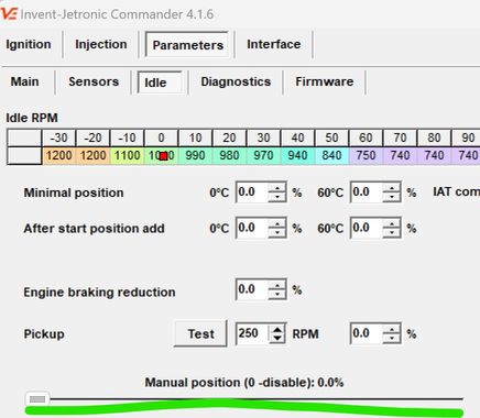
Use the slider to bring the engine RPM close to your desired idle speed.
Important for Audi idle valves – they have a built-in emergency position:
- 0% – valve is partially open (emergency mode).
- 0% to ~25–30% – valve closes.
- Above 30% – valve opens again.
- Therefore, the minimum usable position for Audi valves must be at least 25–30%.
When the RPM is correct:
- Note the slider position that keeps the desired idle speed when the engine is warm.
- Enter a slightly lower value into “Min position at 60 °C”.
- Example: If the idle is stable at 800 RPM with the manual slider at 36%, set the Min value to 33%.
For cold starts:
- Set “Min position at 0 °C” a little higher than the warm value.
- Example: If the Warm value is 33%, set the Cold value to 36%.
- Later, when the engine is cold, recheck and adjust if needed.
Exit manual mode:
- Move the slider back to 0.
- Stop the engine and start it again.
- The idle should now be stable under automatic control.
💡 Tip: This method allows you to quickly determine the correct valve positions without trial-and-error in the settings menu, and ensures smooth idle both warm and cold.
If manual adjustment does not work
If the RPM is still high, no matter what you do:
- Physically block (clamp) ICV pipeline
- RPM should drop, at least 200 RPM below normal.
If RPM remains high:
- Look for air intake in the intake manifold
- Check the throttle stop (it may not be closing completely)
If the revs dropped when blocked:
- Turn off the engine
- Remove the RCH valve from the engine
- Turn on the ignition (do not start the engine!)
- Use the “Manual mode” slider to change the position
- Visually check whether the valve flap moves according to the commands
If the flap does not move:
- Check the electrical connection of the valve
- Measure the resistance of the valve windings
- The valve may be damaged and need to be replaced
Fuel injection system settings
Initial injection settings are required to adjust the calibration to a specific engine.
Preparing for adjustment
![]()
-
Preparing for road tests
-
Find a road free of traffic
- Preferably a flat section or a slight incline
-
Make sure the engine is fully warmed up (80-90°C)
-
System settings
-
Turn on Lambda control
- Turn off Adaptation
-
Clear the accumulated adaptation data (click the “Clear adaptation” button)
-
Cooling the engine compartment
-
Drive for 3-5 minutes in a calm mode to cool and ventilate the engine compartment. This will ensure stable sensor readings.

Mixture settings
-
Driving mode
-
Drive at 2700-3300 rpm
- Press the accelerator pedal so that the pressure sensor (DAT) shows 80-95 kPa
-
Important: Do not press the pedal “to the floor”! A stable partial load mode is required
-
Adjustment
-
Observe the “Lambda correction” indicator
- Adjust the “Mixture correction under load” parameter
-
Goal: Lambda correction should be close to 0 (±2-3%)
-
Stopping the car
-
Stop, leaving the engine running
-
Make sure the RPM has stabilized at idle speed
-
Idle speed adjustment
-
Observe the “Lambda correction” at idle speed
- Adjust the “Mixture correction at idle speed” parameter
-
Goal: Lambda correction should be around 0 (±2-3%)
-
Repeat the cycle
Repeat the entire process 3-4 times:
- Driving under load → adjustment
- Idling → adjustment
- Driving under load → check
- Idling → check
Why repeat?
Mixture correction under load and at idle are interdependent. Changing one parameter affects the other.
Completion
- Enable adaptation
Once stable results are achieved, enable the adaptation system.
What does adaptation do?
- Collects statistics on engine operation in different modes
- Automatically adjusts injection to changes in engine operation
- Compensates for component wear, temperature changes, fuel quality, etc.
Adaptation works correctly if:
- Lambda corrections remain within ±5-10%
- The engine runs stably in all modes
-
There are no errors in the ECU diagnostics
-
Saving settings
-
Save the calibration to a file with a descriptive name
- Create a backup copy of the settings
-
It is recommended to save several versions at different stages of calibration
-
Take a test drive in different modes: city cycle, highway, uphill
Settings overview
Idle
Idle RPM Table
The table specifies the desired idle speed depending on the engine temperature. Typically, the idle speed is higher when the engine is cold to ensure stable operation and faster warm-up, and decreases to the operating value as the engine warms up.
Minimum position
Sets the threshold below which the idle speed control (ICV) does not close. This is necessary to prevent the speed from dropping too low and the engine from stalling. It is recommended to set it 100–200 rpm below the target idle speed.
Addition after start
Sets the additional opening of the ICV immediately after starting the engine. This addition helps to avoid a sharp drop in speed in the first seconds of operation. Too much addition will cause the speed to “freeze” after start-up, too little will cause the engine to stall.
IAT compensation
Air temperature affects its density:
- Hot air is less dense → ICV needs to be opened more to let more air through.
- Cold air is denser → ICV can be opened less.
This parameter sets how much to change the minimum ICV position for every 20 °C deviation from the base air temperature (IAT) of 20 °C.
Pickup
A function that briefly maintains increased revs when the throttle is released so that the engine does not drop sharply to idle.
- Pickup revs — how many revs above idle the regulator should “hold” the revs.
- Pickup percentage — the difference in ICV opening percentage between normal idle speed and pickup. - Test — raises the target RPM by the pickup value for a few seconds, then returns it back. Convenient for tuning
Example:
- RPM = 800, ICV position is 25%.
- Pickup RPM is 300.
- Increase RPM by 300, now RPM is 1100, ICV position is 28%.
- Pickup percentage: 28-25 = 3%.
Manual control
When the slider is set to 0, automatic control is activated — the ECU controls the idle valve according to the configured algorithm.
If you move the slider to any position other than 0, the system will switch to manual control mode. In this case, the valve position will be fixed according to the selected slider value, and the automatic algorithm will be temporarily suspended. As soon as the slider returns to 0, automatic control will resume.
💡 Tip: Manual control mode is useful for:
- testing the valve operation
- checking the engine response to different ICV positions
- temporarily maintaining the speed without changing the basic settings
Idle cut-off
The idle cut-off function is activated when the accelerator pedal is fully released while driving in gear. This saves fuel and reduces emissions.
- Upper limit - RPM above which fuel supply is cut off
- Lower limit - RPM below which fuel supply is resumed
- Delay - Time between releasing the accelerator pedal and the moment when fuel supply is stopped
🔧 Setting tip:
- Too high an upper limit can reduce fuel economy.
- A lower limit that is too low can cause jerks when fuel is re-supplied and RPM drops below idle speed
Corrections
These parameters compensate for changes in engine load when turning the air conditioner on/off or shifting gears to avoid RPM jumps.
- For the air conditioner turned on, you can set the idle speed separately.
- In the On and Off fields, you can set the ICV position correction, which is added or subtracted when the load status changes.
The values are selected experimentally so that the moment of turning the load on or off is imperceptible to the driver.
💡 Example: if the speed drops briefly by 150 rpm when the air conditioner is turned on, you can increase the ICV position in the On field by a few percent until the drop disappears.
PID
Ki setting
Ki is the most important coefficient in the idle speed regulator. It determines the speed at which the revs return to the target value in case of small deviations.
Example: You turn on the air conditioner → the RPM drops → the regulator gradually raises it. The speed of this rise is set by Ki.
Setting procedure:
- Set the IDR value to 800 rpm in the table and wait for stabilization.
- Change the value of XX to 1200 rpm and wait for stabilization again.
- Repeat steps 1–2, selecting Ki so that the speed is set within 3–4 seconds after the change.
Kp setting
Kp determines how quickly the regulator responds to large speed deviations. It is responsible for sudden changes — for example, when you suddenly change the target speed or under heavy loads.
Setting procedure:
- Set IDL = 800 rpm and wait for stabilization.
- Change IDL to 2000 rpm and wait for stabilization.
- Repeat steps 1–2, gradually increasing Kp until you see “oscillation” of the speed (periodic fluctuations), instability, or other undesirable effects.
- Take the resulting Kp value and halve it.
Kd settings
Kd limits the rate of speed drop after reducing the air/fuel supply. It has less impact on idle stability, but if set incorrectly, it can cause rocking.
Tips:
- The default setting is Kd = 0.
- If you want to smooth out the drop in RPM when releasing the throttle, increase Kd until you notice an oscillation when releasing the accelerator.
- Once you notice a oscillation, reduce the Kd value by half.