Mercedes M102
First, remove the air filter. Next, detach the mechanical injectors along with the distributor.
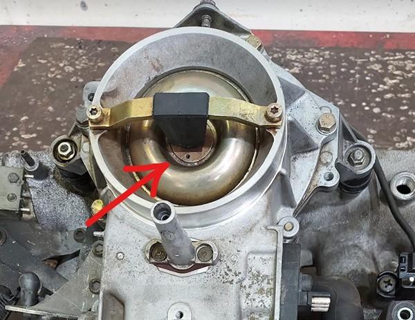
The airflow sensor plate is no longer required. Remove it and secure the movable part beneath with a plastic strap.
Injector rail
To install the injectors, first insert them into the new fuel rail. Next, adjust the two metal brackets on the rail by bending them as needed, and drill holes in each bracket to secure the rail to the intake manifold.
Before drilling, ensure you take accurate measurements and verify that the injectors are fully seated in their housings.

Be sure to hermetically seal the start injector housing with a metal plate and RTV Silicone gasket.
You can also use a rubber tube with the external diameter of the start injector housing and then bolt a screw onto it to hermetically seal it.

Please ensure to thoroughly inspect the EGR piping. Any air leaks in the circuit may cause poor idle performance.

Fuel lines and filter
Install the new fuel lines.

The metal cylinder with three fittings serves as both a fuel filter and a pressure regulator, necessitating the removal of the old original unit.
- Connect the feed line from the fuel pump to the "IN" fitting.
- Attach the return line, which goes back to the tank, directly to the unnamed central fitting.
- Connect the main line leading to the fuel rail to the "OUT" fitting.
Use the three black junctions included in the kit to connect the rubber line to the filter/pressure regulator, ensuring they are securely mounted.

Once the fuel lines are installed, cycle the ignition on and off 5-6 times without engaging the starter to build pressure in the fuel lines.
Thoroughly inspect for any potential leaks.
The fitting features a cone-shaped seal that tightens under fuel pressure. If you notice a leak, try gently moving the fitting back and forth. If it continues to leak, remove it and apply a small amount of oil to the sealing parts.
Idle valve
Clean the valve internals using carburetor cleaner and lubricate them with oil. Avoid WD-40, it is not a suitable lubricant. Bicycle chain lubricant is well-suited for this purpose.
MAP sensor
The precise placement of the MAP sensor is crucial for optimal engine performance. Position it exactly as shown in the photos.
Drill a 13mm hole for the sensor and an 8mm hole for the securing bolt. Apply grease to the drill tip to capture debris. It is recommended to clean the intake manifold thoroughly after drilling to ensure no metal debris remains.
Apply a sealant to fill the hole, ensuring an adequate amount of sealing paste is used due to the rough surface of the intake manifold.
Secure the sensor using the screw. Apply sealant to the threads to prevent air leaks and ensure the sensor remains securely fastened.
Never install the sensor with the wires facing upwards, as this could allow water to run along the cable and damage the connector.
Warning
Installing a MAP sensor in place of a cold start injector is strictly prohibited.

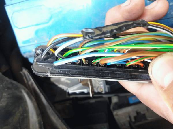
ECU and wiring
Warning
Disconnect the battery when servicing the electrical system. Reconnect the battery only when the engine needs to be started.
The ECU is dust and splash-resistant but not suitable for continuous exposure to water or high-pressure washing. It is recommended to install it in a dry and secure location. Ensure that the ECU is not installed with the cable facing upwards, as this may allow water and moisture to enter the unit.

Warning
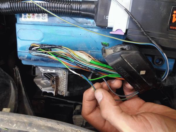
Wire colors may change without prior notice. If wires have text labels, use these labels to identify the purpose of each wire.
The wiring harness for 4-cylinder and 6-cylinder engines is standardized. For a 4-cylinder engine, the connections for the 5th and 6th cylinders will remain unused.
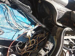
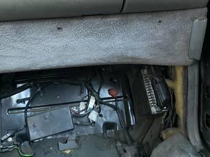
The optimal location for installing the ECU is adjacent to the stock unit. The stock ECU locations are as follows:
- W124: Under the hood, next to the battery
- W126: Front passenger footwell compartment
Extract the necessary wires from the new harness. Connect all new wires in parallel with the stock ECU unless otherwise specified.
Power connection
The black and red wires with the relay and fuse are the power leads. Connect them directly to the battery.
Connections to 25pin ECU
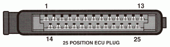
- 1 - IGN
- 3 - IDLE (optional, read Idle Control section below)
- 5 - K-FULL - 9 - IGN
- 8 - Lambda - cut the wire to the stock ECU
- 13 - K-IDLE
- 21 - CLT
- 25 - AN
Connections to 55pin ECU
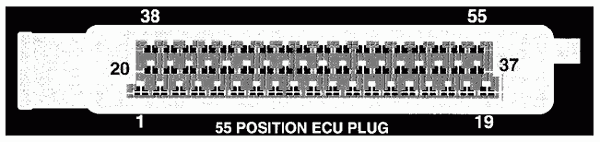
- 9 - IGN
- 13 - Lambda - cut the wire to the stock ECU
- 16 - CLT
- 23 - IDLE (optional, read Idle Control section below)
- 27 - AN
- 46 - K-FULL
- 47 - K-IDLE
Idle control
The stock Mercedes IAC controller is functioning properly and can remain unchanged. If you wish to control the IAC valve using Invent ECU, disconnect the wire from the stock ECU and connect it to the IDLE w
Attention
Only a 2-wire idle valve is supported. For a 3-wire valve, an external circuit is required. For further details, please refer to the Additional Information section at the end of the document.
Lambda sensor
Attention
Ensure the lambda is disconnected from the stock ECU to prevent any interference.
How to install an aftermarket sensor
LPG
Connect the EXT wire to the gas supply valve and activate the LPG mode by EXT input in the settings. The ECU will then adjust to operate on gas fuel.
For carburetted LPG systems, it is unnecessary to disconnect the power from the gasoline injectors. Simply select the Turn off injection option, and the fuel supply will be interrupted by the signal from the EXT. Connect the EXT wire to the gas supply valve and activate the LPG mode by EXT input in the settings. The ECU will then adjust to operate on gas fuel.
Air conditioner
Connect the AC (or EXT) wire to the air conditioner clutch wire. This connection is essential for maintaining the idle RPM when the air conditioner is engaged.
K-Line
Typically, the Bluetooth interface is used to connect to the ECU. However, in rare instances where the Bluetooth connection proves unreliable, the K-Line can be utilized as an alternative.
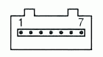
To connect the K-Line cable, you need 3 wires:
- 12V
- Ground
- K-line
Pinout of the K-Line cable:

Pinout of the car OBD2 connector

Other wires
This manual does not mention certain additional wires, which are reserved for future use. Please ensure that any unused wires are isolated and concealed within the harness.
Additional info
Stock ECU pinout
- 1 - Main relay power (Yel)
- 2 - Ground (Brn)
- 3 - Idle speed control valve control (Red/Wht)
- 4 -
- 5 - Full load throttle (Gry/Yel)
- 6 - Speed sensor (Grn/Yel)
- 7 - Ground/Return for cool. sensor (Brn/Wht)-Coolant sensor return for MY 1988 California version
- 8 - Oxygen sensor input (Grn)
- 9 - Fuel pump relay A/T (Grn/Blu)
- 10 - Electro-hydraulic actuator control(Brn/Blk)
- 11 - Altitude sensor (Blu/Red)
- 12 - Electro-hydraulic actuator supply (Brn/Blk)
- 13 - Closed throttle (Brn/Yel)
- 14 -
- 15 - Check engine indicator (Red/Grn)
- 16 - Ignition switch (Vio)
- 17 - Air flow sensor Input (Blu/Wht)
- 18 - Air flow sensor reference (Blu/Grn)
- 19 - A/C compressor (Blu/Yel)
- 20 - Ground (Brn/Red)
- 21 - Coolant temperature sensor (Grn/Red)
- 22 -
- 23 - Diagnostic
- 24 - Deceleration micro-switch input (Gry/wht)
- 25 - TD signal (Grn/Yell)
- 1 - Supply Battery voltage
- 2 - Purge valve
- 3 - 02 sensor heater voltage
- 4 - Idle speed control valve (+)
- 5 - Intake Air temperature sensor
- 6 - Chassis ground
- 7 - Impulse readout, malfunction memory
- 8 -
- 9 - Supply voltage
- 10 - Deceleration fuel shut-off microswitch
- 11 - Start signal
- 12 -
- 13 - 02 sensor signal
- 14 - Intake air temperature sensor
- 15 -
- 16 - Coolant temperature sensor
- 17 -
- 18 - Diagnostic signal 02 sensor heater
- 19 - Ground ECU
- 20 - Start valve activation
- 21 -
- 22 -
- 23 - Idle speed control Valve (-)
- 24 - Check engine warning lamp
- 25 -
- 26 - Data exchange with EZL ECU
- 27 - RPM signal
- 28 - Selector lever position
- 29 - Speed signal
- 30 - Lambda output, on/off ratio
- 31 - Air flow sensor supply voltage
- 32 - 02 sensor wire shielding
- 33 -
- 34 - Air flow sensor ground
- 35 - Ground
- 36 -
- 37 - Electro hydraulic actuator (+)
- 38 - EGR valve
- 39 - Transmission shift point control
- 40 -
- 41 - Supply voltage
- 42 - Air pump control signal
- 43 -
- 44 -
- 45 - A/C compressor engagement signal
- 46 - Full load throttle signal
- 47 - Closed throttle signal
- 48 -
- 49 -
- 50 -
- 51 -
- 52 - Air flow sensor input signal
- 53 -
- 54 -
- 55 - Electro hydraulic actuator (-)
TSZ-h pinout
| Pin | Connection | Signal type | Wire color |
|---|---|---|---|
| 1 | Ignition coil connection 1 | Engine RPM | green |
| 2 | Ground | Power supply (-) | brown |
| 3 | Hall sensor connection 1/- | Power supply (-) | brown/white |
| 4 | Ignition coil connection 15 | Power supply (+) | black |
| 5 | Hall sensor connection 3/+ | Power supply (+) | red/black |
| 6 | Hall sensor connection 2/0 | Ignition timing | green/white |
| 7 | Digijet control unit connection 1 | Engine RPM | green |
Engine wiring harness

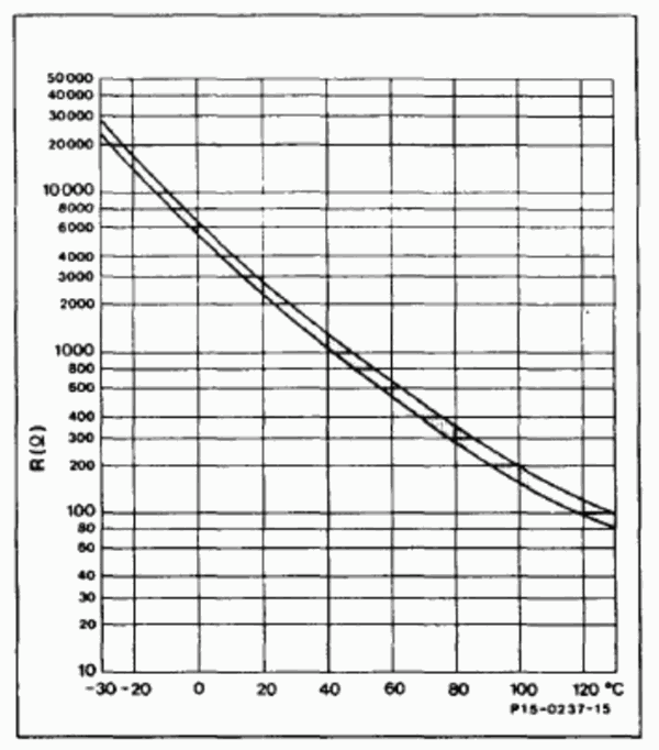
Engine temperature sensor
MAP sensor pinout

Invent Jetronic ECU pinout
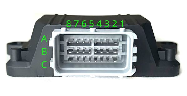
| 8 | 7 | 6 | 5 | 4 | 3 | 2 | 1 | |
| A | IDLE | INJ1 | INJ2 | INJ3 | INJ4 | INJ5 | INJ6 | X1** |
| B | +12V | CLT | TPS | AN | KLINE | EMUL | IDLE SW | FULL SW |
| C | GND | 5V OUT | IAT | MAP | LAMBDA | EXT | DH | AC* |
() - available in version 2.3 (*) - available in version 2.5
3-wire IAC valve
This valve contains two windings: one for opening and another for closing.
An external circuit is necessary to connect this valve. A MOSFET capable of handling over 5A of current and more than 55V of voltage is used (for example IRFZ44)
The dotted line represents the IAC case

Abbreviations
- MAP - absolute pressure sensor
- TPS - throttle position sensor
- IAT - sensor air temperature
- CLT - coolant temperature sensor
- DH - Hall sensor
- AFS - airflow sensor