First start and setup
Before you begin, make sure you have:
- The latest version of Invent Commander software
- A working cable for connecting to the ECU (electronic control unit)
- A stable internet connection to download the program
The ECU controls all fuel delivery and ignition processes. Proper configuration is critical for safe engine operation.
- Downloading the program
Download the [Invent Commander] program from our website:
invent-labs.com/jetronic/files
Why this is important: Using unofficial versions may result in incorrect operation or even damage to the engine.
-
Connecting to the ECU
-
Launch Invent Commander.
- Check that the cable is securely connected
- Click “Connect to ECU”
- Wait for the loading indicator to appear - this means that the program is reading the current settings from the ECU
All calibrations (engine settings) will be automatically downloaded from the ECU to the program. You will see the fields populated with the engine parameters.
If the loading indicator does not appear or if a connection error appears, check the cable, drivers, and COM port number
!!! warning “Warning”
If the message “incorrect version” appears, immediately disconnect from the ECU and do not continue. Download the correct version of Invent Commander from our website.
Using the wrong version can damage the calibration and the engine will not start.
- Using standard calibrations
Calibration is a set of settings that determine how your engine works: how much fuel to supply, how to regulate idle speed, etc.
The package already includes basic calibrations for your engine type. These universal settings are suitable for most engines of this type.
Always start with the basic calibrations. After successful startup and configuration, you can refine them for the specific characteristics of your engine.
Initial configuration
Before starting the engine, you need to configure the basic system parameters.
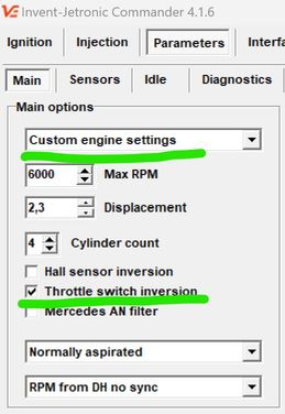
Parameters - General

- Basic parameters - set the engine type, displacement, and maximum RPM. Warning! Exceeding the maximum RPM will result in connecting rod failure.
- Injection settings - specify the injectors you have installed
- Fuel pressure regulator - select 4 bar, no vacuum
- Lambda control and adaptation - turn off (we will configure later)
- LPG mode - turn off (if you use LPG - we will configure later)
- Ignition control - turn on if you use Invent ignition control. However, we recommend performing the first start with the standard ignition system.
- ECU name - Enter a meaningful name, such as “Audi AAR” or “M103 3.0”
- Bluetooth PIN - we recommend leaving the default 0000. But for added security, you can change the PIN code.
!!!warning “Warning” If you have changed the Bluetooth PIN code and forgotten it, you will only be able to connect via the K-Line cable.
Parameters - Sensors
Sensors inform the ECU about temperature, pressure, accelerator pedal position, etc.

General options
- Wideband lambda: Usually, a regular lambda is used, and this option should be disabled. If you have installed a wideband lambda, enable it and set the calibration (you can find it in the wideband lambda manual).
- TPS (Throttle Position Sensor): Normally, limit switches are used, and this option should be disabled. If you have installed a TPS, enable it and set the calibration for the 0% and 100% positions.
- IAT sensor heating compensation (Intake Air Temperature): Enabled for atmospheric engines and disabled for turbo engines.
Temperature sensors
Check the engine and air temperatures. When the engine is cold, both temperatures should be approximately the same (the difference should not exceed 3–5°C).
If the temperatures differ significantly or show unrealistic values
-
Check the sensor pull-up parameters:
-
To the standard ECU - if the sensor is connected in parallel to the standard system. For example, engine temperature.
-
Separate sensor - if the sensor is separate. For example, IAT built into the MAP sensor.
-
Check the sensor voltage on the sensor calibration tab:
When connected to the “Standard ECU”:
- 0V - Sensor not connected, short circuit of the signal wire to ground, break in the signal wire from the standard ECU, damage to the standard ECU
- 5V - no negative on the stock sensor
When connected to a “separate sensor”:
- 0V - short circuit of the signal wire to ground
-
5V - no connection to the sensor, signal wire break, no negative on the sensor
-
Check the sensor calibration:
Try changing different calibrations. If nothing is displayed correctly, switch to manual mode and perform your own calibration.
For manual sensor calibration, you need to enter 3 arbitrary temperature-voltage pairs.
It is convenient to use the following control points: - 0°C: immerse the sensor in ice water and record the voltage readings. - Room temperature (approximately 20°C): record the voltage readings. - 100°C: immerse the sensor in a boiling kettle and record the voltage readings.

Throttle limit switches
The status of the switches is displayed here

These switches show the ECU the position of the accelerator pedal. It is extremely important that these switches work correctly. If they malfunction, the engine may:
- Display MAP error
- Start poorly or not start at all
- Run unsteadily at idle speed
Idle switch
- Make sure that the Idle indicator turns on when the pedal is released.
- Make sure that the Idle indicator turns off when the throttle just starts to move.
- Make sure that the Idle indicator remains off until the pedal is 100% depressed.
- Make sure that the Idle indicator turns on reliably every time you release the pedal.
Check several times at different pedal speeds.
Possible problems:
- Dirty throttle cable, preventing the throttle from returning to the closed position
- Incorrectly adjusted throttle stop, preventing the throttle from returning to the closed position
Full throttle switch
Press the pedal all the way down and look at the full throttle indicator.
- Atmospheric engines: the indicator should come on at approximately 90% of the pedal travel.
- Audi turbo engines: the indicator should come on at 55% of the pedal travel.
!!!feature “Cylinder drying mode” If the full load sensor is triggered while the starter is running, the fuel supply is interrupted. This helps to “dry” flooded spark plugs and start the engine.
If the sensors work in reverse
Symptoms:
- Full load mode is active when the pedal is released
- Idle mode is active when the pedal is pressed
Solution:
- In the settings, select “Manual engine settings”
- Find the “Terminal Inversion” option
- Change its status to the correct sensor operation
Starting the engine
Now you can try to start the engine.
Before starting, make sure that:
- All settings are saved
- The fuel pump is working
- There is pressure in the fuel system
- The battery is charged
- The ECU is connected and the program shows the connection
If the engine does not start:
1: Check the engine speed
- Turn the engine with the starter
- The ECU should show the speed (usually 150-200 rpm when turning)
- If there is no speed, check the speed signal connection (DH or AN, depending on the engine type)
2: Check the injection time
- The injection time should be displayed while the starter is running (for example, 3-8 ms)
- If there is no injection time:
- While cranking with the starter, the full load sensor must be OFF. If it is on, the engine is in “dry” mode. Correct the sensor settings.
- Re-load the basic calibrations.
3: Check the mechanical part
- Fuel pressure in the rail (should be 4 bar)
- Presence of spark on the spark plugs
- Are the spark plugs dry? If they are wet, dry them over an open flame.
- Correct connection of high-voltage wires
After successful start-up
Allow the engine to warm up to operating temperature (80-90°C).
If the RPM jumps from 1000 to 2000 and back again, use the Manual slider on the Parameters > Idle tab to temporarily stabilize the RPM until the engine warms up.
Lambda probe
A lambda probe is a sensor that monitors the quality of the air-fuel mixture.
Initial state (cold sensor)
When the engine is cold, the lambda sensor voltage is 0.45-0.55V. This is normal - the sensor has not yet warmed up to operating temperature.
Troubleshooting
Only diagnose the sensor after the engine has warmed up to operating temperature.
A properly functioning lambda sensor shows a voltage in the range of 0.1-0.2V to 0.7-1.2V, which fluctuates constantly:
- Low voltage (0.1-0.3V) = lean mixture (not enough fuel)
- High voltage (0.7-1.0V) = rich mixture (too much fuel)
If the voltage is 0V:
- Short circuit of the signal wire to ground
- Check the integrity of the wiring
- Check the resistance of the lambda sensor (should be 2-14 kOhm between signal contacts)
If the voltage remains within 0.45-0.55 V:
Check the connections:
- Signal wire is connected correctly
- Sensor ground is connected to the body
Check the lambda sensor heater:
- The heater voltage should be 12V when the engine is running
- The heater resistance should be 8-16 ohms
Sensor replacement: Use a universal lambda sensor:
- Bosch 0 258 986 507
- Bosch 0 258 986 527
- Or another with a heater resistance of 8-16 ohms
Idle speed adjustment
Important: If you are using the factory electronic ignition control, do not alter the Idle RPM table. This will interfere with the factory ignition algorithms and cause Idle RPM instability. You can freely alter this table if you're using a vacuum-based distributor or an Invent ECU-controlled ignition.
Checking the idle speed control (ISC) The engine must be fully warmed up (temperature 80-90°C).
- Go to the Parameters - Idle tab
- Compare the actual speed with the table:
- The actual speed must match the values specified in the table (usually 800-900 rpm)
- The difference must not exceed ±50 rpm
Adjusting Idle RPM Using the Manual Position Slider
When the slider is set to 0, the automatic control is active — the ECU regulates the valve according to its programmed algorithm.
If you move the slider away from 0, you switch to manual control. The valve position now follows your slider setting, and the automatic algorithm is temporarily paused until you return the slider to zero.
💡 Tip: This function is useful for testing or temporarily overriding the system without changing the main tuning settings.
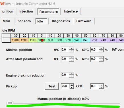
Use the slider to bring the engine RPM close to your desired idle speed.
Important for Audi idle valves – they have a built-in emergency position:
- 0% – valve is partially open (emergency mode).
- 0% to ~25–30% – valve closes.
- Above 30% – valve opens again.
- Therefore, the minimum usable position for Audi valves must be at least 25–30%.
When the RPM is correct:
- Note the slider position that keeps the desired idle speed when the engine is warm.
- Enter a slightly lower value into “Min position at 60 °C”.
- Example: If the idle is stable at 800 RPM with the manual slider at 36%, set the Min value to 33%.
For cold starts:
- Set “Min position at 0 °C” a little higher than the warm value.
- Example: If the Warm value is 33%, set the Cold value to 36%.
- Later, when the engine is cold, recheck and adjust if needed.
Exit manual mode:
- Move the slider back to 0.
- Stop the engine and start it again.
- The idle should now be stable under automatic control.
💡 Tip: This method allows you to quickly determine the correct valve positions without trial-and-error in the settings menu, and ensures smooth idle both warm and cold.
If manual adjustment does not work
If the RPM is still high, no matter what you do:
- Physically block (clamp) ICV pipeline
- RPM should drop, at least 200 RPM below normal.
If RPM remains high:
- Look for air intake in the intake manifold
- Check the throttle stop (it may not be closing completely)
If the revs dropped when blocked:
- Turn off the engine
- Remove the RCH valve from the engine
- Turn on the ignition (do not start the engine!)
- Use the “Manual mode” slider to change the position
- Visually check whether the valve flap moves according to the commands
If the flap does not move:
- Check the electrical connection of the valve
- Measure the resistance of the valve windings
- The valve may be damaged and need to be replaced
Fuel injection system settings
Initial injection settings are required to adjust the calibration to a specific engine.
Preparing for adjustment
![]()
-
Preparing for road tests
-
Find a road free of traffic
- Preferably a flat section or a slight incline
-
Make sure the engine is fully warmed up (80-90°C)
-
System settings
-
Turn on Lambda control
- Turn off Adaptation
-
Clear the accumulated adaptation data (click the “Clear adaptation” button)
-
Cooling the engine compartment
-
Drive for 3-5 minutes in a calm mode to cool and ventilate the engine compartment. This will ensure stable sensor readings.

Mixture settings
-
Driving mode
-
Drive at 2700-3300 rpm
- Press the accelerator pedal so that the pressure sensor (MAP) shows 80-95 kPa
-
Important: Do not press the pedal “to the floor”! A stable partial load mode is required
-
Adjustment
-
Observe the “Lambda correction” indicator
- Adjust the “Mixture correction under load” parameter
-
Goal: Lambda correction should be close to 0 (±2-3%)
-
Stopping the car
-
Stop, leaving the engine running
-
Make sure the RPM has stabilized at idle speed
-
Idle speed adjustment
-
Observe the “Lambda correction” at idle speed
- Adjust the “Mixture correction at idle speed” parameter
-
Goal: Lambda correction should be around 0 (±2-3%)
-
Repeat the cycle
Repeat the entire process 3-4 times:
- Driving under load → adjustment
- Idling → adjustment
- Driving under load → check
- Idling → check
Why repeat?
Mixture correction under load and at idle are interdependent. Changing one parameter affects the other.
Completion
- Enable adaptation
Once stable results are achieved, enable the adaptation system.
What does adaptation do?
- Collects statistics on engine operation in different modes
- Automatically adjusts injection to changes in engine operation
- Compensates for component wear, temperature changes, fuel quality, etc.
Adaptation works correctly if:
- Lambda corrections remain within ±5-10%
- The engine runs stably in all modes
-
There are no errors in the ECU diagnostics
-
Saving settings
-
Save the calibration to a file with a descriptive name
- Create a backup copy of the settings
-
It is recommended to save several versions at different stages of calibration
-
Take a test drive in different modes: city cycle, highway, uphill