Audi 5 cylinders 2.3/2.0
Engine codes AAR,NF,NG,RT,PS Two-piece intake manifold
Remove the intake hose. Also detach the smaller hoses.
Removing mechanical injector
Detach the mechanical injectors along with the distributor.
Remove the upper half of the intake manifold.

Remove the throttle damper located beneath the throttle assembly to allow the installation of the fuel rail.

Remove the MAF air plate and secure the movable part with a plastic strap.

Cut the start injector mount to allow the installation of the fuel rail.

Injector sleeves
Install new injector sleeves.

Fuel rail
Install the injectors into the fuel rail. Lubricate the O-rings with water, then position the rail with the injectors securely in place.
Bend the metal brackets of the rail and drill a hole in each bracket to insert the screw that will secure it to the intake manifold.
Ensure the injectors are fully inserted without any misalignment.

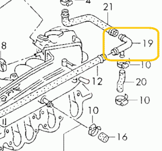
Fuel lines and filter
The fuel lines are now ready for installation.

The metal cylinder with three fittings serves as both a fuel filter and a pressure regulator, necessitating the removal of the old original unit.
- Connect the feed line from the fuel pump to the "IN" fitting.
- Attach the return line, which goes back to the tank, directly to the unnamed central fitting.
- Connect the main line leading to the fuel rail to the "OUT" fitting.
Use the three black junctions included in the kit to connect the rubber line to the filter/pressure regulator, ensuring they are securely mounted.

Once the fuel lines are installed, cycle the ignition on and off 5-6 times without engaging the starter to build pressure in the fuel lines.
Thoroughly inspect for any potential leaks.
The fitting features a cone-shaped seal that tightens under fuel pressure. If you notice a leak, try gently moving the fitting back and forth. If it continues to leak, remove it and apply a small amount of oil to the sealing parts.
Idle control valve (ICV)
Clean the valve internals using carburetor cleaner and lubricate them with oil. Avoid using WD-40, as it is not a good lubricant. Bicycle chain lubricant is well-suited for this purpose.
To install the valve, gently adjust its mount to position the valve closer to the engine block.

In some versions of the engine, the idle air path has a restrictor in the plastic pipe marked yellow, which can prevent the normal operation of the ICV. This restrictor should be deleted.
Intake air heater
The 2.3 engine features an automatic intake air heating shutter designed to maintain the intake air temperature above 10-20 degrees. Ensure this valve is functioning correctly. A malfunctioning valve can cause the throttle valve and IAC to freeze, resulting in difficulties with cold starts and idling.
The precise placement of the MAP sensor is crucial for optimal engine performance. Position it exactly as shown in the photos.
Drill a 13mm hole for the sensor and an 8mm hole for the securing bolt. Apply grease to the drill tip to capture debris. It is recommended to clean the intake manifold thoroughly after drilling to ensure no metal debris remains.
Apply a sealant to fill the hole, ensuring an adequate amount of sealing paste is used due to the rough surface of the intake manifold.
Secure the sensor using the screw. Apply sealant to the threads to prevent air leaks and ensure the sensor remains securely fastened.
Never install the sensor with the wires facing upwards, as this could allow water to run along the cable and damage the connector.
Warning
Installing a MAP sensor in place of a cold start injector is strictly prohibited.

ECU and wiring
Warning
Disconnect the battery when servicing the electrical system. Reconnect the battery only when the engine needs to be started.
The ECU is dust and splash-resistant but not suitable for continuous exposure to water or high-pressure washing. It is recommended to install it in a dry and secure location. Ensure that the ECU is not installed with the cable facing upwards, as this may allow water and moisture to enter the unit.

Warning
Wire colors may change without prior notice. If wires have text labels, use these labels to identify the purpose of each wire.
This is the wiring.

This photo provides an overview of the installation, including key mounting points. The ECU is installed in the position formerly occupied by the mechanical injection distributor. Begin the wiring process by locating the ECU and connecting the injectors. Once these components are connected, the remaining wiring will naturally fall into place.

AFS emulator
Attention
For the RT engine, the AFS emulator is unnecessary. Please proceed to the next chapter.
Plastic box #1 must be removed from the distributor while remaining connected; otherwise, the stock ECU will display an error.

Remove the middle wire from connector #2 and connect it to the EMUL wire.

It should be insulated using shrink tubing or electrical tape.

Measure the resistance between pins 1 and 3 of connector #2. It should be between 3 and 5 kOhms. If the resistance is outside this range, inspect the wires near the connector for signs of oxidation or damage.
Connector #2 should be reconnected to its original position
Hall sensor
Locate the hall sensor connector on the ignition distributor.

Connect the DH wire in parallel to the central wire of the Hall sensor connector.


Lambda sensor
Connect the LAMBDA wire to the signal wire of the lambda probe (refer to the attached photo).
Attention
Ensure the lambda is disconnected from the stock ECU to prevent any interference.

How to install an aftermarket sensor
Throttle position switches
Disconnect the stock connector and measure the resistance of the idle switch. The resistance should be between 0 and 5 Ohms. If it exceeds this range, the switch is likely worn out and should be replaced.

Connect the IDLE SW in parallel with the idle switch wire (position #1 at the connector).
Connect the FULL SW in parallel with the full throttle switch wire (position #3 at the connector). If there is no full throttle switch, insulate this wire. The ECU can operate without it.

Coolant temperature sensor
The CLT wire should be connected in parallel to pin #2 (black-red) of the coolant temperature sensor. If the wire colors differ, use a multimeter to identify the correct pin. The correct pin will show a 5V reading when the connector is disconnected from the sensor.

Idle valve
Disconnect the old idle valve connector and connect the new one labeled "IDLE."
Attention
Only a 2-wire idle valve is supported. An external circuit is required for a 3-wire valve. For further details, please refer to the Additional Information section at the end of the document.
Power
Connect the power wires to the battery and securely mount the main relay in close proximity to the battery.
Attach the COIL +12 wire to the +12V terminal of the ignition coil. This wire is responsible for activating the main relay.
LPG
Connect the EXT wire to the gas supply valve and activate the LPG mode by EXT input in the settings. The ECU will then adjust to operate on gas fuel.
For carburetted LPG systems, it is unnecessary to disconnect the power from the gasoline injectors. Simply select the Turn off injection option, and the fuel supply will be interrupted by the signal from the EXT. Connect the EXT wire to the gas supply valve and activate the LPG mode by EXT input in the settings. The ECU will then adjust to operate on gas fuel.
Air conditioner
Connect the AC (or EXT) wire to the air conditioner clutch wire. This connection is essential for maintaining the idle RPM when the air conditioner is engaged.
K-Line
Typically, the Bluetooth interface is used to connect to the ECU. However, in rare instances where the Bluetooth connection proves unreliable, the K-Line can be utilized as an alternative.
To connect the K-Line cable, you need 3 wires:
- 12V
- Ground
- K-line
Pinout of the K-Line cable:

Pinout of the car OBD2 connector

Other wires
This manual does not mention certain additional wires, which are reserved for future use. Please ensure that any unused wires are isolated and concealed within the harness.
Distributor
Distributor check for AAR engine
Attention
Please ensure that the sensing element is positioned opposite the connector. If the Hall sensor is placed adjacent to the connector, the ignition system may malfunction. It is advisable to replace the sensor with the appropriate one.
The correct hall sensor for the AAR engine is shown in the photo.

- VAG 030 905 065 B
- OSSCA 05430
- JP GROUP 1191400300
Distributor preparation for phased injection
This operation is optional. If performed, it will enable sequential phased injection, which is essential for CNG/LPG conversion. For petrol engines, batch injection is acceptable. However, phased injection can enhance fuel economy slightly during cruising.
These instructions apply regardless of the distributor model or rotation direction. If your distributor differs from the one shown in the photo, follow the instructions to achieve the proper result.
Place a mark on the distributor case

Take off the distributor cap. Turn the crankshaft to align the rotor with the mark.

Position the engine at Top Dead Center (TDC). The rotor should remain aligned with the mark.

Remove the rotor and the plastic cap. Mark the window edge at the center of the hall sensor. The marked window edge should then be widened.

Please widen the window edge by precisely 1.1mm. Ensure maximum precision in this adjustment. If the PHASE indicator in the program becomes unstable, increase the window width by an additional 0.1mm. Conversely, if the window becomes too wide, idling may become unstable.

The cut window will function as the first cylinder marker for the ECU.
Additional info
Wiring diagram for Audi 2.3 AAR engine

- 2 - EVAP valve
- 3 - fuel pump
- 6 - idle valve
- 10 - ignition amplifier
- 11 - ignition coil
- 16 - cold start injector
- 21 - injection pressure regulator
- 36 - throttle switches
- 37 - lambda sensor
- 40 - hall sensor
- 42 - coolant temperature sensor
- 45 - knock sensor
- 50 - airflow sensor
- 51 - atmospheric pressure sensor
- 80 - air conditioner
- 84 - instrument cluster
- 91 - fuel pump relay
- 100 - injection ECU
- 103 - ignition ECU
Wiring diagram for Audi 2.0 RT engine

- 3 - fuel pump
- 6 - idle valve
- 10 - ignition amplifier
- 11 - ignition coil
- 16 - cold start injector
- 21 - injection pressure regulator
- 36 - throttle switches
- 37 - lambda sensor
- 40 - hall sensor
- 42 - coolant temperature sensor
- 45 - knock sensor
- 48 - coolant thermo switch
- 50 - airflow valve position sensor
- 84 - instrument cluster
- 87 - start signal
- 91 - fuel pump relay
- 100 - injection ECU
- 103 - ignition ECU
MAP sensor pinout

Invent Jetronic ECU pinout
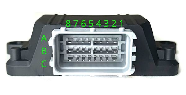
| 8 | 7 | 6 | 5 | 4 | 3 | 2 | 1 | |
| A | IDLE | INJ1 | INJ2 | INJ3 | INJ4 | INJ5 | INJ6 | X1** |
| B | +12V | CLT | TPS | AN | KLINE | EMUL | IDLE SW | FULL SW |
| C | GND | 5V OUT | IAT | MAP | LAMBDA | EXT | DH | AC* |
() - available in version 2.3 (*) - available in version 2.5
3-wire IAC valve
This valve contains two windings: one for opening and another for closing.
An external circuit is necessary to connect this valve. A MOSFET capable of handling over 5A of current and more than 55V of voltage is used (for example IRFZ44)
The dotted line represents the IAC case

Abbreviations
- MAP - absolute pressure sensor
- TPS - throttle position sensor
- IAT - sensor air temperature
- CLT - coolant temperature sensor
- DH - Hall sensor
- AFS - airflow sensor