Audi 5 cylinders 2.3/2.0
Engine codes AAR,NF,NG,RT,PS Two-piece intake manifold
The first thing to do is to remove the intake hose. There are other smaller hoses - these must also be removed.
Removing mechanical injector
Remove mechanical injectors and distributor.
Remove upper half of intake manifold

Remove throttle dampfer (under throttle assembly) which prevents installing fuel rail.

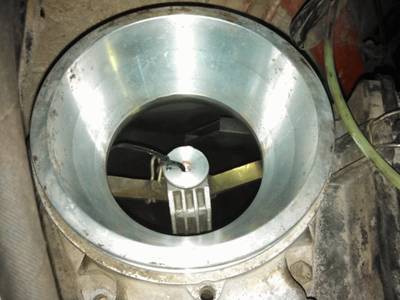
Remove MAF air plate. Secure moving part with plastic strap.
Cut start injector mount which prevents installing fuel rail.
Injector sleeves
Install new injector sleeves. Use engine sealant to secure them.

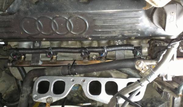
Fuel rail
Install injectors into fuel rail. Then, lubricate o-rings with water, and fit rail with injectors into place. Make sure injectors are fully inserted into plastic guides without skewing.
Mark and drill holes for securing the rail.

Fuel lines and filter
Now the fuel lines can be mounted
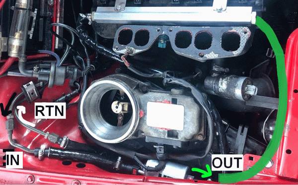
The metal cylinder with three fittings is a fuel filter combined with a pressure regulator, you will need to get rid of the old original one.
- The delivery line that goes from the fuel pump is connected to the "IN" fitting.
- The return line that goes back to the tank is connected directly to the unnamed central fitting.
- The main line that goes to the fuel rail is connected to the "OUT".
Use the the three black junctions provided with the kit to connect the rubber line to the filter/pressure regulator and ensure that they are properly mounted.

After the fuel lines are installed, turn on and off the ignition (without powering the starter) 5-6 times, to build pressure in the fuel lines.
Check carefully for any leaks.
Idle valve
Before installing, clean valve internals with carburettor cleaner, and lubricate with the oil. Don't use WD40, it is not lubricant. To fit the valve, you should slightly bend it's mount, to move valve closer to the engine block.
Intake air heater
The 2.3 engine is equipped with an automatic intake air heating shutter, which does not allow the intake air to cool below 10-20 degrees. Check that this valve is working properly. If the valve is faulty, the throttle valve and IAC may freeze. This leads to problems with the cold start and idling.
MAP sensor
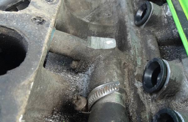
MAP sensor location is really important to ensure a good engine operation. Locate MAP sensor exactly as shown on photo.
Drill 13mm hole for the sensor and 8mm for the bolt that will secure it. Cover the drill tip with grease to catch the debris, it is reccomended to clean the intake manifold after drilling the hole to ensure that no metal debris is left in it.
Seal hole with a sealant. Sufficient sealing paste must be applied because the surface of the intake manifold is rough.
Secure sensor with included screw. Apply sealant to the thread, to prevent air leaks and unscrewing.
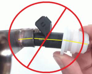
Never install any sensor with the wires upwards, water will flow off the cable and shortcircuit the sensor.
Warning
It is prohibited to install MAP sensor in place of cold start injector.

ECU and wiring
Warning
Disconnect battery when working with the electrical system. Connect battery back only when engine have to be started.
ECU is dust and splashproof. It cannot withstand continuous water contact or pressurized water, so it is reccomended to install it in a dry and safe place. Do not install ECU with cable upwards. In this case, water and moisture will flow off the cable into ECU.

Warning
Wire colors are subject to change. If wires have text labels - use labels to identify wire purpose.
This is the wiring.

This is overview of installation, with some of the mounting points. ECU is located in place of the mechanical injection distributor. You should start wiring with locating ECU and connecting injectors, while manifold is disassembled. The rest of the wiring will find it's place then.

AFS emulator
Attention
For RT engine, AFS emulator is not needed. Skip this chapter.
Plastic box #1 should be removed from the distributor, and left connected, otherwise the stock ECU will show an error.

Cut the middle wire from the connector #2, and connect to the EMUL wire.
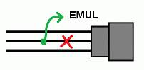
It should be insulated with shrink tubing or electrical tape.

Check the resistance between pin 1 and 3 of the connector #2. It should be 3..5 kOhm. If not - check wires near the connector for oxidation and damage.
The connector #2 is now plugged back into the original place.
Hall sensor
Find the hall sensor connector on the ignition distributor.

Connect DH wire in parallel to the central wire of hall sensor connector.


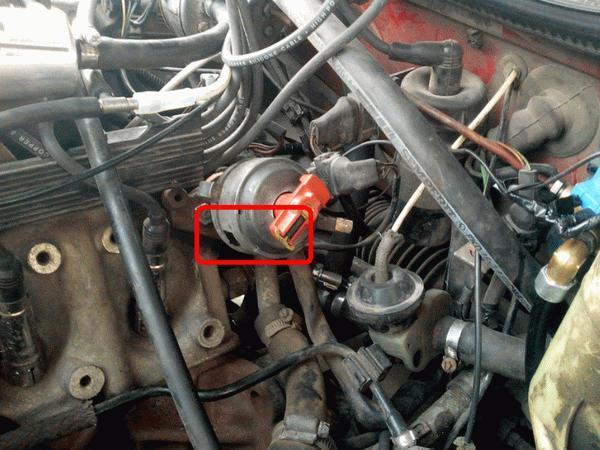
Lambda sensor
Connect the LAMBDA wire to the signal wire of the lambda probe (see on photo).
Attention
Make sure to disconnect the lambda from the stock ECU to avoid interference.

If you don't have lambda sensor, or your sensor is malfunctioning, you should install universal Bosch sensor 0258986507 or 0258006537
Connection diagram:
- white wires - to the lambda heating connector, or to the fuel pump supply
- black - signal to the ECU
- gray - to the ECU ground
Throttle position switches
Disconnect stock connector, and check idle switch resistance. It should be 0..5 Ohm. If higher - switch is worn out, you should replace it.

Connect IDLE SW in parallel to the idle switch wire (#1 at the connector)
Connect FULL SW in parallel to the full throttle switch wire (#3 at the connector)

Coolant temperature sensor
CLT wire is connected in parallel to the coolant temperature sensor pin #2 (black-red)


Idle valve
Disconnect old idle valve connector, and connect new one, labeled IDLE.
Attention
Only 2-wire idle valve is supported. For 3-wire valve, external circuit is needed. For more information, look into additional info section at the end of the document.
Power
Connect power wires to the battery. Secure main relay near the battery.
Connect COIL +12 wire to the ignition coil +12V terminal. This wire is used for switching on the main relay.
LPG
Connect the EXT wire to the gas supply valve, turn on the LPG mode by EXT input in the settings. Now the ECU will adapt to work on gas fuel.
If you have a carburetted LPG system - you do not need to cut the power of gasoline injectors. Check Turn off injection option and fuel will be cut by the signal from the EXT.
Air conditioner
Connect EXT wire to the air conditioner clutch wire. It is used for maintaining idle RPM while air conditioner is operating.
K-Line
Normally, you will use Bluetooth interface to connect to the ECU. In rare cases, BT connection is unreliable, so you can use K-Line instead.
To connect K-Line cable, you should prepare 3 wires:
- 12V
- Ground
- K-line
Pinout of the K-Line cable:

Pinout of the car OBD2 connector

Other wires
There are other wires, not mentioned in this manual. They are reserved for future use. Isolate and hide unused wires into the harness.
Distributor
Distributor check for AAR engine
Attention! Make sure that the sensing element is opposite to the connector! If the hall sensor is located next to the connector, the ignition system will not work correctly! You should replace the sensor with the correct one.

Correct hall sensor for the AAR engine:

- VAG 030 905 065 B
- OSSCA 05430
- JP GROUP 1191400300
Distributor preparation for phased injection
This is optional operation. If done - you'll get sequential phased injection. It is crucial for CNG/LPG conversion. For petrol - you can use batch injection and be perfectly happy with the engine operation. Phased injection on petrol can bring some fuel economy while cruising.
This manual is not dependent on the distributor model and rotation direction. If your distributor is different from the photo - just strictly follow the manual, and you will get the right result.
Find high voltage pin, connected to the 1st cylinder

Make mark on the distributor case

Take off the distributor cap. Turn the crankshaft to align the rotor with the mark.
Now, set the engine to the TDC. Rotor should still point to the mark.

Take off the rotor and the plastic cap. Mark the window edge at the center of the hall sensor. This window edge should be widened.

You should widen the window edge by 1.1mm. Make it with maximum precision. If PHASE indicator in the program will be unstable - widen the window by another 0.1mm If window will be too wide - idling will be unstable.

Additional info
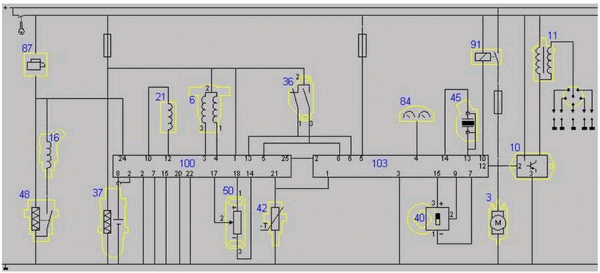
Wiring diagram for Audi 2.3 AAR engine

- 2 - EVAP valve
- 3 - fuel pump
- 6 - idle valve
- 10 - ignition amplifier
- 11 - ignition coil
- 16 - cold start injector
- 21 - injection pressure regulator
- 36 - throttle switches
- 37 - lambda sensor
- 40 - hall sensor
- 42 - coolant temperature sensor
- 45 - knock sensor
- 50 - airflow sensor
- 51 - atmospheric pressure sensor
- 80 - air conditioner
- 84 - instrument cluster
- 91 - fuel pump relay
- 100 - injection ECU
- 103 - ignition ECU
Wiring diagram for Audi 2.0 RT engine
- 3 - fuel pump
- 6 - idle valve
- 10 - ignition amplifier
- 11 - ignition coil
- 16 - cold start injector
- 21 - injection pressure regulator
- 36 - throttle switches
- 37 - lambda sensor
- 40 - hall sensor
- 42 - coolant temperature sensor
- 45 - knock sensor
- 48 - coolant thermo switch
- 50 - airflow valve position sensor
- 84 - instrument cluster
- 87 - start signal
- 91 - fuel pump relay
- 100 - injection ECU
- 103 - ignition ECU
MAP sensor pinout

Invent Jetronic ECU pinout
View at the ECU connector
| 8 | 7 | 6 | 5 | 4 | 3 | 2 | 1 | |
| A | IDLE | INJ1 | INJ2 | INJ3 | INJ4 | INJ5 | INJ6 | |
| B | +12V | CLT | TPS | AN | KLINE | EMUL | IDLE SW | FULL SW |
| C | GND | 5V OUT | IAT | MAP | LAMBDA | EXT | DH | AC* |
(*) - АС input is available starting from ECU version 2.3
3-wire IAC valve
It has two windings - one for opening and the other for closing.
To connect this valve, an external circuit is required. A MOSFET with a current of >5A and a voltage of >55V is used.
The dotted line indicates the IAC.

Abbreviations
- MAP - absolute pressure sensor
- TPS - throttle position sensor
- IAT - sensor air temperature
- CLT - coolant temperature sensor
- DH - Hall sensor
- AFS - airflow sensor